
The OpenGL ES Shading Language
Description
The focus of this chapter is to understand how to write shader programs in conjunction with Candera. In OpenGL ES 2.0 / 3.0, the OpenGL ES Shader Language (GLSL ES) is used as programming language for creating various effects, from simple texturing to stunning effects, like bump mapping, anisotropic lighting, and so forth. The programmable pipeline of ES 2.0 is also valid for ES 3.0, but the shading language has been extended somewhat. OpenGL ES 2.0 uses the GLSL ES 1.0 shading language. OpenGL ES 3.0 uses the GLSL ES 3.0 shading language.
For more detailed information you may refer to the GLSL ES specification or to the OpenGL ES 2.0 Programming Guide. Additionally, vast resources of GLSL as well as GLSL ES shader tutorials can be found on the internet. GLSL is to a large extent compatible to the GLSL ES shader language.
See also:
For hints on how to optimize shaders refer to
- Optimizing Shader Programs in Application Development Best Practices
A Minimal Shader Program
Here is a small example to demonstrate the syntax of GLSL ES. The following example simply transforms the vertices into clip coordinate space, forwards texture coordinates, and applies a texture to the rasterized image.
Vertex Shader
This is the vertex shader code of our example:
#ifndef GL_ES

// An OpenGL environment might not support precision qualifiers. Thus, define them to void.
#define lowp
#define mediump
#define highp
#define precision

#endif

/*
 Uniforms
 */
uniform mat4 u_MVPMatrix;       // Model-View-Projection Matrix

/*
 Attributes
 */
attribute vec4 a_Position;
attribute vec2 a_TextureCoordinate;

/*
 Varyings
 */
varying mediump vec2 v_TexCoord;

/*---------------------------------- MAIN ------------------------------------*/
void main(void)
{
    /* Transform vertex into world space */
    gl_Position = u_MVPMatrix * a_Position;

    v_TexCoord = a_TextureCoordinate;
}
Purpose of this vertex shader is simply to transform the incoming a_Position vertex attribute into clip coordinate space, using the model-view-transformation matrix provided as uniform u_MVPMatrix. Additionally, the incoming attribute a_TextureCoordinate is forwarded to the next stage as varying v_TexCoord and will be available in the fragment shader, if a varying with same name exists. In the fragment shader the incoming value will be interpolated between the vertices of a primitive.
The preprocessor directives (#ifndef #define ... #endif) simply check if the shader is running inside a OpenGL ES or OpenGL rendering pipeline and defines the precision qualifiers to nothing if not running in an ES context. This simply transforms the OpenGL ES shader into a compatible OpenGL shader if necessary, as the only differences are the precision qualifiers.
Fragment Shader
This is the fragment shader code of our example:
#ifndef GL_ES

// An OpenGL environment might not support precision qualifiers. Thus, define them to void.
#define lowp
#define mediump
#define highp
#define precision

#endif

/*
 Uniforms
 */
uniform sampler2D u_Texture;

/*
 Varyings
 */
varying mediump vec2 v_TexCoord;

/*---------------------------------- MAIN ------------------------------------*/
void main(void)
{
    gl_FragColor = texture2D(u_Texture, v_TexCoord);
}
Purpose of this fragment shader is to query the color from the passed sampler u_Texture (handle to a texture) at the address of the incoming varying v_TexCoord and to apply this color to the fragment. This will be the color that is finally displayed, if all succeeding tests have passed. Nothing more, nothing less. It can be observed that the varying variable v_TexCoord has the same name than in the vertex shader.
The preprocessor fulfills the same purpose as in the vertex shader.
Output
The following image shows the result of rendering a vertex buffer (containing vertices of a cube) using the vertex and fragment shader above. The model-view-projection matrix was set to rotate the cube, a 2D texture was applied to it as sampler2D u_Texture.
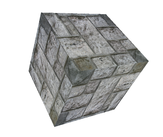
Basic OpenGL ES 2.0 Shading Language elements
Basic OpenGL ES 2.0 / 3.0 Shading Language elements
The subject of this section is to comprehend the syntax and structure of the vertex and fragment shaders, presented in the lean shader example, see the previous A Minimal Shader Program. Knowledge of C like languages is assumed to understand GLSL syntax.
Declaring Uniform variables
The qualifier uniform is used to declare immutable variables in vertex or fragment shaders, which are set from client code.
-
Uniforms are global variables, and therefore have to be declared outside of function scope.
In our example the following uniforms are used:
uniform mat4 u_MVPMatrix;
u_MVPMatrix is used to pass the model-view-projection matrix to the vertex shader object, which is used to transform all vertices.
uniform sampler2D u_Texture;
u_Texture is the handle to the texture, which is addressed using the texture2D function.
Declaring Varying variables
The qualifier varying is used in two different ways.
- In the vertex shader it is used to declare variables which are written by the shader, and are further passed over primitive assembly and rasterization. Therefore they get interpolated inside the fragments, which are finally input of the fragment shader.
- In fragment shader the same keyword is used to declare incoming variables. Like uniforms these varying variables are global, and therefore have to be defined outside function scope.
-
Varying variables have to have exactly the same name and type in vertex and fragment shader, otherwise linking of them together will fail.
In our example only one varying is used:
varying mediump vec2 v_TexCoord;
v_TexCoord is used to pass the texture coordinates stored inside the vertices attributes to the fragment shader. While passing the OpenGL ES 2.0 pipe they get interpolated between the vertices of a primitive. Inside the fragment shader the interpolated coordinates are finally used to address the texture sampler, in order to determine the final color of a fragment.
Precision Qualifiers
Compared to "full" GLSL, GLSL ES has the specialty of precision qualifiers, which can be used to declare variables to be handled with different precision. Reason for this language feature was the focus on embedded hardware, which might provide faster medium precision floating point or integer units than the high precision ones. Precision of a float or uniform variable is defined using one of the qualifiers lowp, mediump or highp.
For further details on how these kinds of variables behave when they get assigned to each other, or when arithmetic is used with different precision, please refer to the GLSL ES standard.
In our example this was used for the varying variable in both shaders:
varying mediump vec2 v_TexCoord;
Function Declaration
Functions can be defined like in almost every other C-like programming language. Function definitions follow the syntax shown below:
returnType functionName (type0 arg0, type1 arg1, ... , typen argn)
{
    //Method Body
    return returnValue;
}
Like in C they can be prototyped with leaving the method body and closing the declaration using a semicolon. For calling the function of course it has to be defined.
A function then is called using its name followed by a list of arguments in parentheses (or empty ones if no arguments apply).
Function names can further be overloaded as long as the argument types are different.
Return and argument types can be any type allowed in GLSL (such as int, float, double, vec4, mat4, sampler2D, ...). Additionally returnType can be void, which indicates that the function doesn't return anything. Arrays can be passed as argument, but cannot be returned.
In our examples above only one function is defined for the vertex and the fragment shader:
void main(void)
{
    //Main Body
}
The main function is mandatory for both vertex and fragment shader, this is the entry point to the shader. It has to take no argument and has to return no value (void). From here further functions can be called.
Writing Output Data
There are two possibilities to output a vertex shaders result.
- The first and mandatory way is to write the transformed vertex coordinates in clip coordinate space to gl_Position. This one is required to be set by any vertex shader. The behavior is undefined, if gl_Position is not set.
- The second, optional way is to use variables declared as varying to output any desired data, as described in the varying section. The content of varyings is passed as input to the fragment shader, the fragment shader will receive the interpolated values per transformed primitive.
Results of fragment shaders are written to gl_FragColor, which is a 4-component vector (vec4) representing the final color that will be displayed if all further tests pass. It is possible to use the discard keyword to abort a fragment shader based on conditions, which might be useful if some fragments shall be completely skipped, in this case also no depth or stencil value will be written. This trick can be applied for e.g. creating an interlace mask for interlaced stereoscopic 3D.
Accessing textures
One very important function of fragment shaders is to fetch colors from textures and use it for composing the final gl_FragColor. This task is done using the GLSL ES built-in function texture2D:
vec4 texture2D (sampler2D sampler, vec2 coord );
where sampler is the handle to the texture to query the color from, coord is the texture coordinate pair to address a certain "texel" (point of a texture).
The sampler2D variable has to be passed as uniform to the shader, this is the OpenGL handle to the texture in VRAM. In our simple fragment shader example the color read from the texture is passed directly as gl_FragColor, therefore the resulting cube has the wall image directly applied.
The following snippet shows how the uniform containing the texture handle is declared.
uniform sampler2D u_Texture;
The following incoming varying vec2 is used to address a texel.
varying mediump vec2 v_TexCoord;
The final color is queried from the texture using the texture2D function.
gl_FragColor = texture2D(u_Texture, v_TexCoord);
-
Texturing can also be used in vertex shaders. This can be used to e.g. realize a technique called Displacement Mapping where the vectors stored inside a texel are not interpreted as color but as offset being applied to the current vertex position. Consequently, a displacement map can be used e.g. to transform a flat plane to a terrain.
Also other types of samplers (e.g. samplerCube) and corresponding texture addressing functions (e.g. textureCube) exist, again for more details please have a look at the GLSL ES Standard.
Commenting shader programs
Comments in GLSL are delimited, as in other C-like languages, by
/* and */
or
// and EOL.
Everything in between these delimiters will be ignored by the compiler.
Other language features, data types and function library.
For a more detailed view on how to specify control structures, available data types, built-in functions, and other language features please refer to the GLSL ES Standard.