
Vertex Geometry Builder
Description
The Candera::VertexGeometryBuilder class helps effectively build Candera::VertexGeometry objects.
Procedural Geometry
Example: Wireframe Cube with LineList
First example shows how to generate a wireframe cube using a Candera::LineList object.
The vertex geometry will be generated procedurally using a Candera::VertexGeometryBuilder object (e.g. m_builder).
Vertex Element Format: Position and Color
At the beginning we have to specify what kind of information will be set in the vertices. Of course we need information about the position and, optionally, for an improved visual effect, we could also add color information.
    // Set the data type to be used: position & color
    m_builder.SetVertexElementFormat(VertexGeometry::Position, 0, VertexGeometry::Float32_3);
    m_builder.SetVertexElementFormat(VertexGeometry::Color, 0, VertexGeometry::Float32_4);
Vertex Data: Position
The position information for the vertices is obtained from the array c_cubeData which, in fact, stores the coordinates of the points A and G. The coordinates for the rest of the vertices are obtained relatively to this points (e.g. F(XA, YG, ZG) or D(XG, YA, ZA)
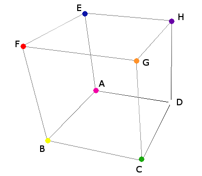
// Coordinates for the points A & G
static const Float c_cubeData[2][3] = {
    {-1.0F, -1.0F, -1.0F },
    {1.0F, 1.0F, 1.0F }
};
VertexGeometryBuilder: Set Vertex Elements
Because the LineType property of the LineList object will be set to LineType::Lines, the vertex buffer will have to contain a pair of vertices for each line of the cube: 2 vertices/line * 12 lines = 24 vertices.
    // Set the position & color information for each vertex
    // Line segment AD
    m_builder.SetVertexElement(VertexGeometry::Position, 0, c_cubeData[0][0], c_cubeData[0][1], c_cubeData[0][2]); // A
    m_builder.SetVertexElement(VertexGeometry::Color, 0, 1.F, 0.F, 1.F, 1.F); // magenta
    // Increment the vertex cursor
    m_builder.IncrementVertexCursor();
    m_builder.SetVertexElement(VertexGeometry::Position, 0, c_cubeData[1][0], c_cubeData[0][1], c_cubeData[0][2]); // D
    m_builder.SetVertexElement(VertexGeometry::Color, 0, 1.F, 1.F, 1.F, 1.F); // white
    m_builder.IncrementVertexCursor();
    // Line segment AB
    m_builder.SetVertexElement(VertexGeometry::Position, 0, c_cubeData[0][0], c_cubeData[0][1], c_cubeData[0][2]); // A
    m_builder.SetVertexElement(VertexGeometry::Color, 0, 1.F, 0.F, 1.F, 1.F); // magenta
    m_builder.IncrementVertexCursor();
    m_builder.SetVertexElement(VertexGeometry::Position, 0, c_cubeData[0][0], c_cubeData[0][1], c_cubeData[1][2]); // B
    m_builder.SetVertexElement(VertexGeometry::Color, 0, 1.F, 1.F, 0.F, 1.F); // yellow
    // ...
Create Vertex Buffer
Create a Candera::VertexBuffer object and attach to it the vertex geometry obtained from the Candera::VertexGeometryBuilder:
    VertexGeometry* vertexGeom = m_builder.GetVertexGeometry();
    SharedPointer<VertexBuffer> vertexBuffer = VertexBuffer::Create();
    static_cast<void>(vertexBuffer->SetVertexGeometry(vertexGeom, VertexBuffer::VertexGeometryDisposer::Dispose));
    vertexBuffer->SetPrimitiveType(VertexBuffer::Lines);
Create LineList using the Vertex Buffer
Attach the vertex buffer to LineList object:
    // Create and configure the line list object
    m_lineList = LineList::Create();
    m_lineList->SetAppearance(Appearance::Create());
    m_lineList->GetAppearance()->SetMaterial(Material::Create());
    m_lineList->GetAppearance()->GetMaterial()->SetEmissive(Color(1.0F, 1.0F, 0.0F));
    m_lineList->GetAppearance()->SetShader(m_shaderLightMaterial);
    m_lineList->SetLineType(LineList::Lines);
    m_lineList->SetWidth(1.0);
    m_lineList->SetIntersectionTestEnabled(false);
    m_lineList->SetVertexBuffer(vertexBuffer);
    m_lineList->SetScopeMask(ScopeMask(false));
    static_cast<void>(m_lineList->SetScopeEnabled(1, true));
    m_lineList->SetRenderingEnabled(true);
    m_lineList->SetName("Wireframe");
    static_cast<void>(m_lineList->Upload());
Wireframe Cube Result
The image below shows the resulting wireframe cube:
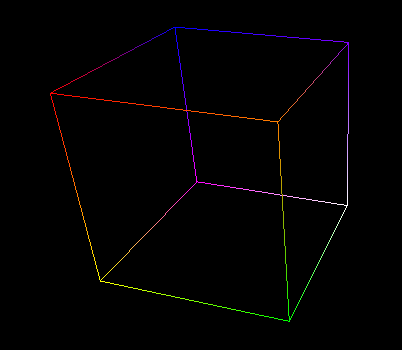
-
For an easier manipulation of the widget in SceneComposer all the shaders are hardcoded in the source file and then created by the widget at the initialization time.
Alternatively obtain shaders from Candera::AssetProvider (e.g. GetAssetProvider()->GetShader("...")) in case the application uses an asset library.
Indexed Geometry
Example: Solid Cube from one Triangle Strip
The next example will show how to create a solid cube from one triangle strip using a Candera::Mesh object. In this case the cube is determined by only 14 vertices which have to be ordered in a special way.
The figure below presents a cube unfolded and a possible solution of ordering the vertices:

Indexed Vertex Sequence
The vertex sequence is stored in the c_index_order array, encoding the order:
- G->C->F->B->A->C->D->H->A->E->F->H->G->C.
Each array element represents an offset it the vertex buffer.
// The vertex sequence - triangle strip
static const UInt16 c_index_order[] = { 12, 11, 7, 3, 0, 11, 1, 17, 0, 5, 7, 17, 12, 11 };
The vertex geometry builder object used in the previous example has already 24 vertices set with position and color information. Because only 14 vertices out of 24 are needed in this case and, also, because their sequence has to be different, an index buffer is added:
    // Change the order of the vertices using indexes
    for (Int index = 0; index < 14; index++) {
        // Define the value of the index
        m_builder.SetIndexElement(c_index_order[index]);
        // Increment the index cursor
        m_builder.IncrementIndexCursor();
    }
Create TriangleStrip Vertex Buffer
Create the vertex buffer using the geometry from the builder:
    VertexGeometry* vertexGeom = m_builder.GetVertexGeometry();
    SharedPointer<VertexBuffer> vertexBuffer = VertexBuffer::Create();
    static_cast<void>(vertexBuffer->SetVertexGeometry(vertexGeom, VertexBuffer::VertexGeometryDisposer::Dispose));
    vertexBuffer->SetPrimitiveType(VertexBuffer::TriangleStrip);
Create Mesh using the Vertex Buffer
Configure mesh and attach the vertex buffer:
    m_mesh = Mesh::Create();
    m_mesh->SetVertexBuffer(vertexBuffer);
    m_mesh->SetAppearance(appearance);
    m_mesh->SetRenderingEnabled(false);
    m_mesh->SetName("SolidNonTextured");
    static_cast<void>(m_mesh->Upload());
Solid Cube Result
The image below shows the resulting solid cube:
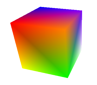
Remove & Add Vertex Elements
Example: Textured Cube
In this example the vertex geometry builder object will be used to generate the vertex geometry for a textured cube.
Adding texture to a mesh requires that its vertices should contain specific information like normal and texture coordinate. Also, the color information is no longer needed so it can be removed:
    // Vertex Elements Manipulation
    // Remove color data associated to the vertices
    m_builder.RemoveVertexElement(VertexGeometry::Color,0);
    // Add data type to be used: texture coordinate & normal
    m_builder.SetVertexElementFormat(VertexGeometry::TextureCoordinate, 0, VertexGeometry::Float32_2);
    m_builder.SetVertexElementFormat(VertexGeometry::Normal, 0, VertexGeometry::Float32_3);
Vertex Data: Normals and Texture Coordinates
After adding the new data types for the vertices it is time to add the corresponding information. First, add normals for vertices:
    // Move the cursor to the first vertex
    m_builder.SetVertexCursor();
    for (UInt32 i = 0; i < m_builder.GetVertexCount(); i++ )
    {
        m_builder.SetVertexElement(VertexGeometry::Normal, 0, 0.0F, 0.0F, 1.0F);
        m_builder.IncrementVertexCursor();
    }
In order to map the UV texture coordinate values correctly, the cube faces should be drawn using 4 vertices per face, so, in this case, all 24 vertices will be used. Of course, the vertex order has to be adjusted.
The new vertex order is stored in the c_indexDataTexturedCube array.
// Vertex order - textured cube
static const UInt16 c_indexDataTexturedCube[24] = {
    1,17,0,5,
    2,6,3,7,
    9,8,11,12,
    13,14,19,21,
    15,23,16,22,
    4,10,20,18
};
Now, reorder the vertices:
    // Overwrite the index buffer
    // Move the cursor to the first index
    m_builder.SetIndexCursor();
    for (UInt32 i = 0; i < m_builder.GetVertexCount(); i++ )
    {
        // Define the value of the index
        m_builder.SetIndexElement(c_indexDataTexturedCube[i]);
        m_builder.IncrementIndexCursor();
    }
The vertices of each face of the cube should be set with texture coordinate information as shown below:
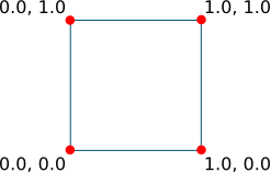
Set the texture coordinates for vertices:
    Int idx = 0;
    for (Int nb_of_faces = 0; nb_of_faces<6; nb_of_faces++) {
        for (Int u=0; u<=1; u++) {
            for (Int v=0; v<=1; v++) {
                //Set the position of the vertex cursor
                m_builder.SetVertexCursor(c_indexDataTexturedCube[idx]);
                m_builder.SetVertexElement(VertexGeometry::TextureCoordinate, 0, static_cast<Float>(u), static_cast<Float>(v));
                idx++;
            }
        }
    }
The vertex buffer is created and configured in the same way as in the previous example.
The mesh setup is also similar but, unlike the solid cube, the textured cube appearance has to be set with a texture and a texture shader.
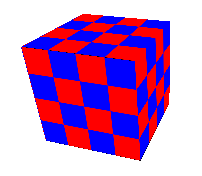
Textured Cube Result
Here is the final result:
Range Data Usage
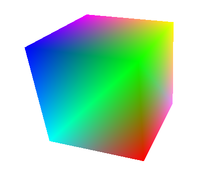
Example: Solid Cube using Range Data
This example will show how to create a solid cube as in the second example but using range data.
First, all existing data from the vertex geometry builder is removed.
    // Clear all data stored by the builder
    m_builder.Clear();
The vertex data is taken from the two buffers c_positionData and c_colorData.
static const Float c_positionData[8][3] = {
    { -1.0F, 1.0F, 1.0F},
    { 1.0F, 1.0F, 1.0F},
    { -1.0F, -1.0F, 1.0F},
    { 1.0F, -1.0F, 1.0F},
    { -1.0F, 1.0F, -1.0F},
    { 1.0F, 1.0F, -1.0F},
    { -1.0F, -1.0F, -1.0F},
    { 1.0F, -1.0F, -1.0F}
};

static const Float c_colorData[8][4] = {
    { 0.0F, 0.0F, 1.0F, 1.0F},
    { 0.0F, 1.0F, 0.0F, 1.0F},
    { 0.0F, 1.0F, 1.0F, 1.0F},
    { 1.0F, 0.0F, 0.0F, 1.0F},
    { 1.0F, 0.0F, 1.0F, 1.0F},
    { 1.0F, 1.0F, 0.0F, 1.0F},
    { 1.0F, 1.0F, 1.0F, 1.0F},
    { 1.0F, 0.5F, 1.0F, 1.0F}
};
The vertex sequence is taken from the array c_indexData.
// Range data index
static const UInt16 c_indexData[] = {3, 2, 1, 0, 4, 2, 6, 3, 7, 1, 5, 4, 7, 6 };
Use the methods Candera::VertexGeometryBuilder::SetVertexElementRange and Candera::VertexGeometryBuilder::SetIndexElementRange to add the required information.
    // Add position, color and an index from range data
    // Splice values to the position buffer starting with the first vertex
    static_cast<void>(m_builder.SetVertexElementRange(VertexGeometry::Position, 0, 0, VertexGeometry::Float32_3,
        8, 3*sizeof(Float), c_positionData ));
    // Splice values to the color buffer starting with the first vertex
    static_cast<void>(m_builder.SetVertexElementRange(VertexGeometry::Color, 0, 0, VertexGeometry::Float32_4,
        8, 4*sizeof(Float), c_colorData ));

    // Splice values to the index buffer starting with the first index
    static_cast<void>(m_builder.SetIndexElementRange(0, sizeof(c_indexData)/sizeof(UInt16),c_indexData));
The vertex buffer configuration and the mesh setup are identical with the ones from the second example.
Here is the final result:
Concatenate Geometries
VertexGeometryBuilder::SpliceGeometry
In some cases it might be useful to concatenate two vertex geometries. This can be done by using the Candera::VertexGeometryBuilder::SpliceGeometry method as shown below:
    m_builder.SpliceGeometry(0, 0, vertexGeometry1);
    m_builder.SpliceGeometry(vertexGeometry1->GetVertexCount(), vertexGeometry1->GetIndexCount(), vertexGeometry2);
    vertexGeometry1cat2 = builder.GetGeometry();