
Cameras and Render Targets
Description
Content specified in a Candera scene graph is rendered by configuring at least one camera on it. The render result of the camera is projected on a so called render target.
This chapter gives an overview about cameras and render targets in Candera.
Go to EGL Context Handling to skip the introduction and proceed with the first example for this topic.
Camera Orientation
- modifying the "rotation" part of Transformable (Candera::Transformable::SetRotation),
- setting the two orientation vectors:
- the local "LookAt" vector which can be set by the functions Candera::Camera::SetLookAtVector, Candera::Camera::LookAtWorldPoint, Candera::Camera::RotateAroundWorldAxis
- the local "Up" vector, set by the function Candera::Camera::SetUpVector
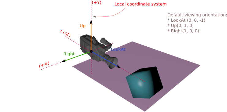
- setting a "LookAt-Node." If such a node is set the camera will always look at that node. This behavior overrides other rotation transformations set by the methods mentioned above. The node can be set by the function Candera::Camera::SetLookAtNode.
The viewing orientation of the Candera::Camera2D can be controlled only by modifying the local rotation using the Candera::Transformable2D::SetRotation function.
See also:
- Camera Gizmos in SceneComposer User Manual
Camera Projections
Candera::Camera::SetProjection is analogous to choosing a lens for the camera.
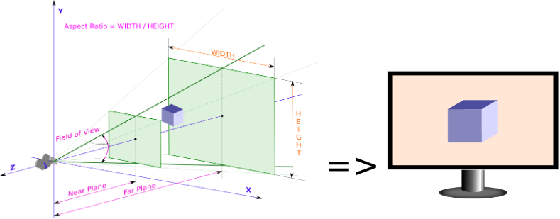
- Candera::PerspectiveProjection: This is the most commonly used projection. It provides proper visual effects depending on the distance between 3D objects and the camera projecting them. Specify the field of view (FoV) in degrees and the aspect ratio to adjust the camera lens properly.
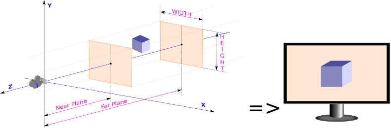
- Candera::OrthographicProjection: This tutorial chapter has a use case where an OrthographicProjection is needed instead of a PerspectiveProjection. This projection type provides an orthogonal view on the projection plane.
- Candera::GenericProjection is an option to specify an arbitrary projection matrix.
Camera Viewport
Use Candera::Camera::SetViewport to specify a rectangular region on the render target for projecting the camera output. The position and size of the viewport should be given as normalized screen coordinates [0..1]. If the viewport aspect ratio differs from the aspect ratio of the Camera's projection matrix, the final render result will appear stretched or compressed. The default value for viewport to cover the complete render target area is: left 0, right 0, width 1, height 1.
The example below shows how to set the viewport in case of two cameras connected to the same display render target:
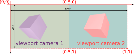
    perspectiveProjection->SetAspectRatio(1.3333f)); // (1280/2)/480
    ...
    m_camera1 = Camera::Create();
    m_camera1->SetViewport(Candera::Rectangle(0.0f, 0.0f, 0.5f, 1.0f));
    m_camera1->SetRenderTarget(m_gdu->ToRenderTarget3D());
    m_camera1->SetProjection(perspectiveProjection);
    m_camera1->SetClearMode(m_clearMode1);
    m_camera1->SetClearModeEnabled(true);
    m_camera1->SetSwapEnabled(true);

    m_camera2 = Camera::Create();
    m_camera2->SetViewport(Candera::Rectangle(0.5f, 0.0f, 0.5f, 1.0f));
    m_camera2->SetRenderTarget(m_gdu->ToRenderTarget3D());
    m_camera2->SetProjection(perspectiveProjection);
    m_camera2->SetClearMode(m_clearMode2);
    m_camera2->SetClearModeEnabled(true);
    m_camera2->SetSwapEnabled(false)
Candera::Camera2D::SetViewport works similarly but in 2D context. The default value for a viewport of a 2D camera are:
- left: 0
- right: 0
- width: -1
- height: -1
-
The viewport position and size of a Candera::Camera2D are given in pixels.
Below is presented an example similar with the one above but adapted for 2D.
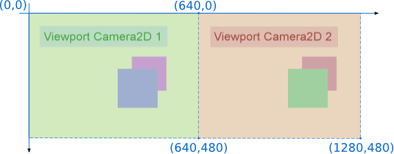
    m_camera2D_1 = Camera2D::Create();
    m_camera2D_1->SetViewport(Candera::Rectangle(0.0f, 0.0f, 640.0f, 480.0f));
    m_camera2D_1->SetRenderTarget(m_gdu->ToRenderTarget2D());
    m_camera2D_1->SetClearColor(Color(0.8f, 0.9f, 0.7f, 0.1f));
    m_camera2D_1->SetClearColorEnabled((true);
    m_camera2D_1->SetSwapEnabled(true);

    m_camera2D_2 = Camera2D::Create();
    m_camera2D_2->SetViewport(Candera::Rectangle(640.0f, 0.0f, 640.0f, 480.0f));
    m_camera2D_2->SetRenderTarget(m_gdu->ToRenderTarget2D());
    m_camera2D_2->SetClearColor(Color(0.9f, 0.8f, 0.7f, 0.1f));
    m_camera2D_2->SetClearColorEnabled((true);
    m_camera2D_2->SetSwapEnabled(false);
Render Targets
A render target is a buffer where the video card draws pixels for a scene that is being rendered. Consequently, once a camera is configured, it must be linked to a render target to specify the target for the camera output.
Display and Offscreen Render Targets
There are basically two different types of render targets (Candera::GraphicDeviceUnit) available in Candera, which can render only 2D content, only 3D content or mixed 2D/3D content:
- Display/Onscreen Render Targets: A frame buffer is used as render target and directly linked to a Display.
- DisplayTarget3D
- DisplayTarget2D
- Mixed2D3DDisplayTarget
- Offscreen Render Targets: A frame buffer is used as render target and can be used as image source in the same or another scene.
- OffscreenTarget3D
- OffscreenTarget2D
- OffscreenTarget2Dto3D
- OffscreenTarget3Dto2D
- Mixed2D3DOffscreenTarget
For iMX6 device there is one more type of render target: Candera:SoftwareLayer. More details about this can be found in Software Layers chapter.
Device Capabilities
For an overview about what kind of render targets are supported on which device please refer to: Device Specific Documentation
Following is an overview about what kind of render targets are supported on which device:
| Device | Number of Displays Supported | Types of Layers Supported | Unit Types |
|---|
See also:
- Link Camera to Render Target in SceneComposer User Manual
Render Target Lifetime
- Create: A graphic device unit (GDU) which hosts a render target and/or an image source can be created with function DevicePackageInterface::CreateGraphicDeviceUnit.
- Upload: Subsequently, in order to utilize GDU an upload to video memory is required, which is processed by calling function GraphicDeviceUnit::Upload on GDU object.
- Destroy: In order to destroy video and system memory resources associated to GDU call functions GraphicDeviceUnit::Unload and DevicePackageInterface::DestroyGraphicDeviceUnit in exactly that order.
In general, follow the sequence below to upload and unload GDUs:
- Construction:
- 1.) Upload all displays
- 2.) Upload all onscreen framebuffers (WindowSurface)
- 3.) Upload all offscreen framebuffers (FramebufferBufferObject)
- Destruction:
- 1.) Unload all offscreen framebuffers (FramebufferBufferObject)
- 2.) Unload all onscreen framebuffers (WindowSurface)
- 3.) Unload all displays
Render Buffer Swapping and Clearing
Render Buffer Swapping
If the draw target operates on multiple buffers after each rendering cycle the presentation buffer is exchanged with the current background buffer, on which was written during the cycle.
For this, three interfaces are available:
- Candera::RenderTarget::SetAutoSwapEnabled(bool enabled): if true, render target buffers are swapped automatically, when a camera within the render target has been rendered. Default: false
- Candera::Camera::SetSwapEnabled(bool enable): if true, buffers are swapped automatically after rendering the according camera. Default: false
- Candera::RenderTarget::SwapBuffers(): Trigger buffer swapping 'by hand'
It is very important to control buffer swapping in the application correctly:
- If swapping is never done, the display will stay black
- If buffers are swapped too often, the display will flicker.
The application doesn't need to swap its render targets in case:
- the render target is set to swap automatically. For this, set the render target property "SetAutoSwapEnabled" to true.
- the proper camera is set to swap automatically. For this, set the camera property "SwapEnabled" to true.
-
If you use more than one camera on a render target, take care to enable swapping only for the last camera (highest sequence number).
Render Buffer Clearing
The render buffer can be cleared by one of the cameras attached to the render target or by the render target itself by the means of a shared clear mode object.
Render Buffer Clearing by Camera
Camera2D interface offers two methods related to render buffer clearing. First one, Candera::Camera2D::SetClearColor(), sets the clear color and the other one, Candera::Camera2D::SetClearColorEnabled(), sets whether the clear is performed or not at each render call.
    camera2D->SetClearColor(Candera::Color(0.5f, 0.5f, 1.0f, 1.0f));
    camera2D->SetClearColorEnabled(true);
Comparing to the 2D context where only the color buffer needs to be cleared, in 3D, Camera has to clear three buffers: color, depth and stencil. Camera performs the clearing using a Candera::ClearMode object which is attached to it using the method Candera::Camera::SetClearMode().
    Candera::ClearMode clearmode;
    clearmode.SetClearColor(Candera::Color(0.5f, 1.0f, 0.5f, 1.0f));
    clearmode.SetColorClearEnabled(true);
    clearmode.SetClearDepth(1.0f);
    clearmode.SetDepthClearEnabled(true);

    camera3D->SetClearMode(clearmode);
-
Candera::Camera and Candera::Camera2D clear only the area specified by the viewport.
Render Buffer Clearing by Render Target
The render buffer clearing using the render target is useful especially when the camera viewport is not covering the entire render target. The 2D render target clears the color buffer using a shared clear mode object as shown in the example below:
    Candera::SharedClearMode2D::SharedPointer shClearMode2D = SharedClearMode2D::Create();
    shClearModem2D->GetClearColor() = Candera::Color(0.0f, 0.5f, 0.5f, 1.0f);
    m_gdu2D->ToRenderTarget2D()->SetAutoClearEnabled(true);
    m_gdu2D->ToRenderTarget2D()->SetClearMode(shClearModem2D);
In 3D, the clearing it realized in a similar way but the render target will use a shared clear mode object which has attached a clear mode object.
    Candera::ClearMode clearmode;
    clearmode.SetClearColor(Candera::Color(0.8f, 0.4f, 0.4f, 1.0f));
    clearmode.SetColorClearEnabled(true);
    clearmode.SetClearDepth(1.0f);
    clearmode.SetDepthClearEnabled(true);

    Candera::SharedClearMode::SharedPointer shClearMode = Candera::SharedClearMode::Create();
    shClearMode->SetClearMode(&clearmode);

    gdu->ToRenderTarget3D()->SetClearMode(shClearMode);
    gdu->ToRenderTarget3D()->SetAutoClearEnabled(true);
Example
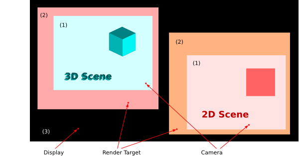
Consider two cameras & render targets, 2D and 3D, connected to a common display (see picture below). The clearing is enabled on both cameras and render targets, while clear colors for the render targets and cameras are all different.
- Background color of area (1) is set by the clear color of Camera2D respectively the 3D Camera in the 3D Scene, since the clearing setting of the camera overrides the one from the render target.
- Since the camera viewport is smaller than the render target size, area (2) is cleared by the render target.
- Area (3) cannot be cleared because it is not covered by any of the two render targets.
SceneComposer Example Solution
In SceneComposer, the configuration of render target clearing in 2D context is done similarly to the one of a 2D camera: select the Render Target and, in the Properties panel, enable the "Auto Clear Enabled 2D" property and set the clear color by modifying the "Clear Mode 2D" property.
In 3D context, the activation of auto-clearing on a render target implies to create first a ClearMode: in the Solution Explorer, right click on any of the folders from "Solution" and choose "Add->New Item...->ClearMode". In the "Add new item" dialog enable and set an appropriate value for the Color Clear, Depth Clear and Stencil Clear and then press "OK". Now, select the 3D Render Target and, in the Properties panel, set "Auto Clear Enabled" property to "True" and then click on the "Clear Mode" property and select the previously created ClearMode. An example of usage the render target auto-clear feature in SceneComposer is presented in the solution RenderTargetAutoClearSolution example in folder cgi_studio_player/content/Tutorials/07_RenderTargetsCameras.
Software Layers
Overview
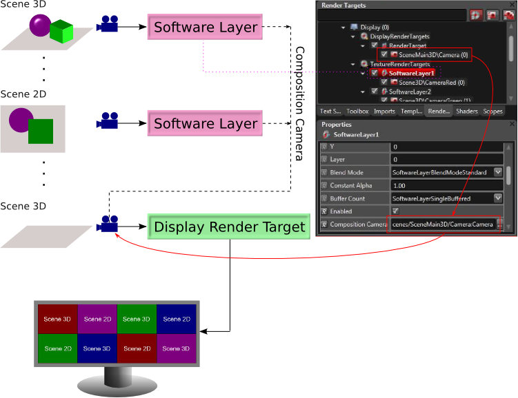
The Candera::SoftwareLayer is a special mixed graphic device unit supported only on specific device packages. This graphic device unit, despite the fact it is a texture render target, it is not meant to be used as Image source in a texture but rather it acts like a display render target by the means of a composition camera (see diagram below).
-
Software Layers are not supported on all devices! Software Layers are supported on iMX6. An example solution for this concept can be seen in cgi_studio_player/content/Tutorials/07_RenderTargetsCameras solution.
Configuration
-
For a correct behaviour of the scene editor the composition camera has to be placed in a separate scene.
The number of software layers which can be blended in one pass is limited by the number of texture units specific for the device.
- For specific devices the maximum number of software layers is 8.
Each of these virtual layers can have a distinct blending mode, buffer settings, size or position, but all have to use the same composition camera, the Candera::Camera which is linked to the display render target:
-
The software layers are delimited by a 1 px border. If needed, this border can be disabled using the "BorderEnabled" property.
Layer Order
The software layers are ordered depending on the value set for the Layer property, bigger values meaning that the layer will be closest to the composition camera rendering the main scene.
Blend Modes
Following blend modes are supported for Software Layers:
| Source | Destination | Constant Alpha | Blend Mode | Formula | Output |
|---|---|---|---|---|---|
| 0.5 | SoftwareLayerBlendModeStandard | SRC * SRC.A + DST * (1 - SRC.A) | |||
| SoftwareLayerBlendModePreMultiplied | SRC + DST * (1 - SRC.A) | ||||
| SoftwareLayerBlendModeConstantAlpha | SRC * CNS.A + DST * (1 - CNS.A) | ||||
| SoftwareLayerBlendModeSimultaneousAlpha | SRC * SRC.A * CNS.A + DST * (1 - SRC.A * CNS.A) | ||||
| SoftwareLayerBlendModeSimultaneousPreMultiplied | SRC * CNS.A + DST * (1 - SRC.A * CNS.A) | ||||
| SoftwareLayerBlendModeOff | SRC |
For more information about alpha blending please read also the Blending chapther.
Insides
As any other graphic device unit the Candera::SoftwareLayer can be created via Candera::DevicePackageInterface::CreateGraphicDeviceUnit.
- Use Candera::DevicePackageDescriptor::GetUnitTypes to get its type handle as a second parameter for the offscreen render target categories.
- The SoftwareLayer properties are specified in the Candera::SoftwareLayerProperties class (see Candera::SoftwareLayer::GetSoftwareLayerProperties)
- and the pixel format information is kept in the Candera::GlFrameBufferProperties class (see Candera::SoftwareLayer::GetFrameBufferProperties()).