
Programmable Graphics Pipeline
Description
When working with shaders, a fundamental knowledge of OpenGL ES 2.0 / 3.0 and the corresponding GLSL ES 1.0 / 3.0 shader language is required, to unleash the freedom and power programmable graphic pipelines provide, compared to the former fixed-function graphics pipeline. The focus of this chapter is to give the reader a basic overview of the OpenGL ES 2.0 / 3.0 rendering pipeline, in order to understand how OpenGL ES 2.0 / 3.0 works, and how the advantages that come with shader programming can be leveraged.
OpenGL ES 2.0 / 3.0 Graphics Pipeline
The OpenGL ES 2.0 / 3.0 Graphics Pipeline determines how data stored in Vertex Buffers and Textures get processed, in order to produce the final image in the framebuffer (which might be displayed on screen or an off-screen render buffer, see Tutorial 7).
-
Only a simplified view is described here, in order to enable the reader to gain a basic knowledge and comprehension of shader programs, their purpose and principles of operation.
Basically the data passed to the OpenGL ES 2.0 API (encapsulated by Candera::Engine3D::Core Classes, such as Candera::VertexBuffer, Candera::Texture) is stored in Vertex Buffers and Texture Memory.
Vertex Buffers get processed by the Vertex Shader unit, and are transformed and projected from model space into world space, and finally screen space. This data is then assembled into primitives (triangles, lines, points) which subsequently get rasterized to determine which pixels are covered by the primitive and are subject to be rendered.
-
Pixels at this stage of the pipeline, are known as fragments, as they might be discarded by the pipeline in subsequent tests and thus never appear as a pixel in color buffer.
The Fragment Shader then takes these fragments, interpolates the attributes of each vertex inside a primitive and combines these with the colors stored in Texture Memory. After applying some tests, blending and dithering, the final pixel gets written to the Framebuffer. The following image describes this workflow graphically.[2]
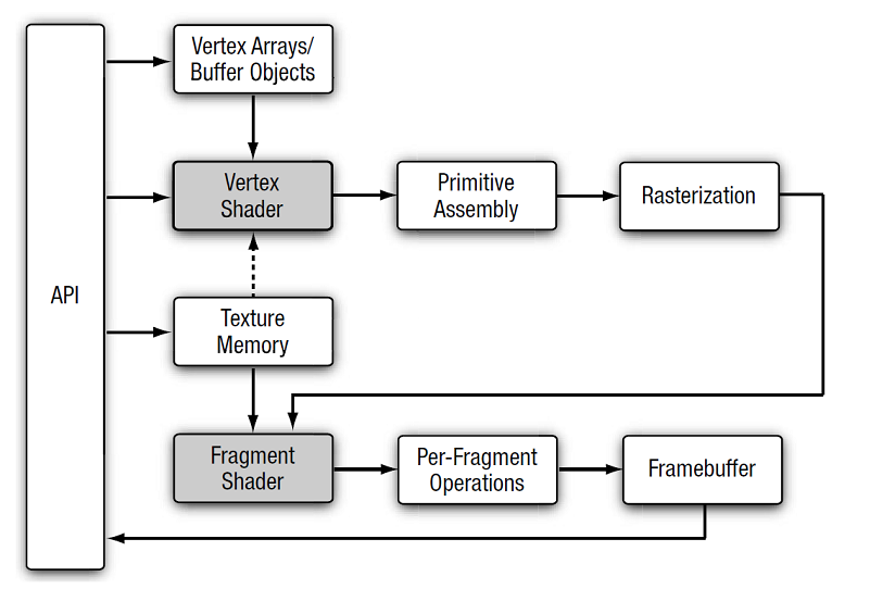
The following table shortly describes the single stages in the image above.
| Stage | Description |
| API | OpenGL ES application programming interface, this is encapsulated by Candera. |
| Vertex Arrays / Buffer Objects | Buffer in VRAM that stores vertices along with their vertex attributes. Vertex attributes are typically positions, normals, texture coordinates, colors etc. which are stored for every vertex of every primitive. This array is filled and managed by Candera::VertexBuffer. |
| Vertex Shader | Processes the data stored in vertex buffer, and transforms them to screen coordinates with depth. |
| Primitive Assembly | Assembles the data processed shaded vertices into individual geometric primitives that can be drawn. Such primitives can be triangles, lines or points. The necessary settings here are also set in Candera::VertexBuffer. |
| Rasterization | Single primitives are converted to a set of two-dimensional fragments (describing the normalized position in the framebuffer). This is the input data to the fragment shader. |
| Texture Memory | Texture memory is the location in VRAM where textures (2D or CubeMaps. In OpenGL ES 2.0, 1D and 3D textures are only supported through extensions) are stored. This memory is filled and managed by Candera::Texture. |
| Fragment Shader | Fragment shader takes the processed fragments as input, and combines them with the data stored in Texture memory. This stage results in assigning the fragment a color. |
| Per-Fragment Operations | Each fragment is tested, to determine whether it is to be drawn. Blending and dithering operations conclude the pipeline. Various configurations are set, using Candera::RenderMode. Here Depth-, Stencil-, Scissoring Tests, Blending and Dithering apply. |
| Framebuffer | Includes color, depth-, and stencil buffer to store final render output. |
This chapter described the stages Vertex Shader and Fragment Shader. The next chapter explains how to interact and control programmable shaders.
Programmable Shaders
Description
This chapter is about user-programmable Vertex and Fragment Shader units.
Chapters
Shader Programs Introduction
Programmable Shaders
Before OpenGL 2.0 and OpenGL ES 2.0, Vertex Shader and Fragment Shader units had fixed functionality. The common wording for this is "fixed function pipeline". Since OpenGL 2.0 and OpenGL ES 2.0 the behavior of these shaders became user-programmable. The wording is "programmable pipeline".
Being able to program these stages of the pipe offers a whole new set of opportunities. The shaders still have the same inputs and outputs, but the way in which these outputs are generated can now be defined by the user. Also, using user-defined variables may now be passed to the shader.
Programmable Vertex Shader units offer the possibility of manipulating every single vertex of geometry in a user-defined way, using different input attributes, user-defined uniform variables or even textures to compute the final outcome.
Fragment operations allows the final color to be computed from different sources, as the user wishes. This gives the user the powerful ability to produce almost every desired effect. Typical examples range from per pixel-lighting, normal mapping, multi-texturing, environment mapping (using cubemaps) and many more.
However, there is one small disadvantage. The "fixed-function" pipeline has been replaced by the programmable one, which forces the user to re-implement any behaviour of the "fixed function pipeline", which may be required.
Shader Programs
A shader program is the user-generated code that gives the pipeline its user-defined behavior. A user of OpenGL ES 2.0 / 3.0 has to provide this before rendering any object. In Candera this is encapsulated in Candera::Shader as described in Tutorial 3. A shader program consists of two parts, a vertex shader and a fragment shader, which must be linked together to form the shader program.
These two shader objects are generated from a special programming language known as the OpenGL Shading Language (ES) or GLSL (ES), which uses a C-like syntax. The method in which the shader is passed, is platform dependent. On Desktop GPU's the shader compiler is normally integrated into the graphics driver, and therefore the GLSL source is directly passed to Candera::Shader::SetVertexShader and Candera::Shader::SetFragmentShader, while on some target devices, pre-compiled binaries are expected.
For a detailed step-by-step tutorial see the corresponding section. What follows is an overview on how the different types of shader objects work and which data they process.
Vertex Shaders
Vertex shader objects are the program objects that give Vertex Shaders user-defined behavior. The following image illustrates the input and output data processed by this kind of shader object..[3]
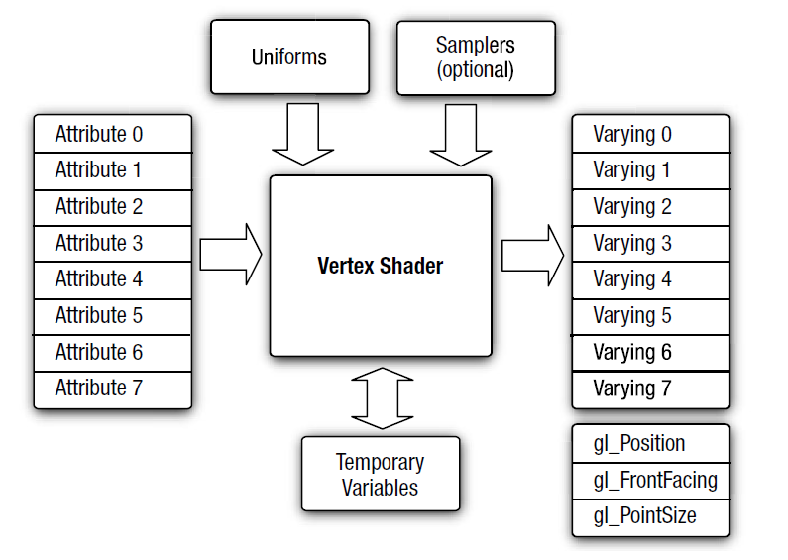
Attributes are the data components of a vertex, describing values such as position, normal, texture coordinates, color, tangent or binormal. This data is stored inside the vertex buffer and is the input that comes over the OpenGL ES 2.0 / 3.0 pipeline. The vertex shader is executed once for each incoming vertex.
Uniforms and Samplers (actually also passed as uniform) are user-defined input variables that are passed to every instance of a shader. A user defines it once for a shader object, but all shaders get this value. This input can consist of 4x4-, 3x3-, 2x2- matrices, 2-4 component vectors, single values and arrays, all of type Float, Int or Bool. Special sampler uniforms are handles to uploaded 2D- or CubeMap Textures. Textures can also be used in vertex shaders, a good example for this is Displacement Mapping, where the values stored in the textures colors are interpreted as vectors to offset the vertices. This can be used e.g. to transform a plane into a virtual terrain.
Varyings are user-defined output variables of a vertex shader, which are finally interpolated between all members of a primitive after primitive assembly. These can have the same data types as the incoming uniforms, except for sampler handles. For each fragment, the interpolated data then gets passed into the fragment shader. Typically texture coordinates are forwarded from the vertex buffer to the fragment shader in this way, but you can pass any kind of data where it makes sense to interpolate between the vertices of a primitive.
Temporary Variables are variables which live inside the scope of one shader object. They can have the same data types as uniforms or varyings.
Vertex Shader Special Output Variables gl_Position and gl_PointSize are only available in vertex shaders. gl_FrontFacing is not available in OpenGL ES, but only in full OpenGL. gl_Position is reserved for writing the vertex position in homogeneous coordinates (after transforming into world space, camera space and projected to screen space). This value has to be written by every vertex shader, in order to enable primitive assembly and rasterization. Not setting gl_Position results in undefined behavior. gl_PointSize can be used optionally to set the point size of vertices, if the primitive type points is used.
Fragment Shaders
Fragment shader objects are the program objects that give Fragment Shaders user-defined behavior. The following image illustrates the input and output data processed by this kind of shader object.[4]
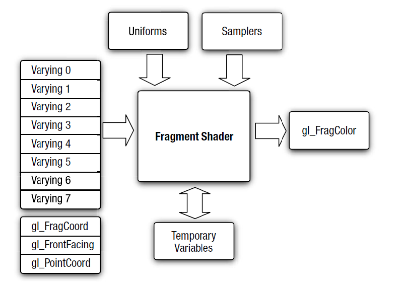
Varyings are user-defined input variables for a fragment shader. These values have to match the varyings in the vertex shader (data type and name). A fragment shader is called once for each rendered pixel, which implies that the incoming varyings hold the interpolated value of all varyings passed per primitive from the vertex shader.
Uniforms and Samplers are user-defined input variables that are passed to every instance of a shader. They have the same meaning as in the vertex shader. Additionally uniforms in vertex and fragment shaders can have the same data type and name. In this case, when passing the variables value, it'll be passed to both the vertex and the fragment shader.
Temporary Variables are variables which live inside the scope of one shader object. They can have the same data types as uniforms or varyings.
Fragment Shader Special Input Variables gl_FragCoord, gl_FrontFacing and gl_PointCoord are read-only variables only available in fragment shaders. gl_FragCoord holds the window relative coordinates x,y,z and 1/w values for the fragment. Z-value is the value that's used for depth testing after passing the Fragment Shader stage. gl_FrontFacing holds a boolean value which determines whether the fragment belongs to a front facing primitive (true) or not (false). gl_PointCoord specifies where the fragment is located, within a point primitive. If the primitive is of type line or triangle, this value is undefined.
Fragment Shader Special Output Variable gl_FragColor is used to write the output of the fragment shader into the current fragment. gl_FragColor holds a 4-component vector of floats ranging from 0.0 to 1.0 for each component. This describes the RGBA color of the current fragment, used by the rest of the OpenGL ES 2.0 / 3.0 rendering pipeline. This will be the color you actually see on the screen or will be blended against another color, if the fragment passes all succeeding tests. Not setting this value will result in undefined colors on the screen.
References
The knowledge presented in this tutorial is a summary of:
[1] Munshi, Aaftab; Ginsburg, Dan; Shreiner, Dave: OpenGL ES 2.0 Programming Guide. Addison Wesley, 2008. ISBN 978-0-321-50279-7
The images were taken from:
[2] Munshi, Aaftab; Ginsburg, Dan; Shreiner, Dave: OpenGL ES 2.0 Programming Guide. p.4. Addison Wesley, 2008. ISBN 978-0-321-50279-7
[3] Munshi, Aaftab; Ginsburg, Dan; Shreiner, Dave: OpenGL ES 2.0 Programming Guide. p.5. Addison Wesley, 2008. ISBN 978-0-321-50279-7
[4] Munshi, Aaftab; Ginsburg, Dan; Shreiner, Dave: OpenGL ES 2.0 Programming Guide. p.8. Addison Wesley, 2008. ISBN 978-0-321-50279-7