
GettingStartedControls Part 1
This part of the tutorial describes how to configure the Home Scene of this solution.
The scene is built up using imported images and configuring various controls (such as TellTale, Gauge, DigitalClock, TextValue, Text, FlipBook). The use of a ForwardValue behavior will ensure that the Speed Gauge and an additional textual display will show the same value at any time.
Finally, the Panel is started to verify the coherency of the Speed Gauge and the speed's textual display.

Setting up the SceneComposer Solution
- Create a new solution using the Empty Solution template and save it as shown in Creating a new Solution.
- A new solution is created and saved.
- A new solution is created and saved.
- Activate the Render Targets panel on the top right and select [ Display (0) ]. In the Properties panel below change the display's X and Y Resolution.
- The horizontal and vertical resolution of the display will be defined.
- The aspect ratio of the display will be calculated automatically.
Target Item Setting Value X Resolution 1024 Y Resolution 768 
Preparing the Scene
- In the Solution Explorer panel on the top left select "Scene3D" (under "Solution - Scenes") and delete it either using the <delete> key or via the context menu [ Delete ] as described in Delete a Scene.
- A "Delete Items" dialog will popup.
- Please resolve all dependencies with "Delete Usage Item" and click [ OK ].
- Scene3D will be deleted.
- Scene3D will be deleted.
- Select "Scene2D" and rename it to "SceneHome" either by pressing <F2> on your keyboard or via the context menu "Rename".
- The scene's name has been changed to "SceneHome"

- The scene's name has been changed to "SceneHome"
- In the Solution Explorer panel double-click the "SceneHome" to open it in the Scene Editor (see also 2D Scene Editor).
- "Scene Home" will be displayed in the Scene Editor on the right of the Solution Explorer panel.
- The content of this scene will be displayed in the Scene Tree panel below the Solution Explorer panel.
- Save the solution using the <Ctrl+S> keyboard combination or via the menu bar File - Save Solution.
- The asterisk next to the filename in the SceneComposer window's titlebar will disappear, indicating that the solution has been saved.
It might be a good idea to make a backup of your solution now! If you destroy something during execution of the following steps you always have the possibility to restart with a clean solution. To make a copy just make a copy of the GettingStartedControls folder or create a copy by archiving into a zip file.
Import Images
The images needed for this solution will be imported. Some of them will be used as plain static images, but most will be used to configure controls.
- In the menu bar choose [ Import ] - [ Import Resources... ] as described in How to Import Resources.
- [ Import Resources ] dialog will be opened
- [ Import Resources ] dialog will be opened
- Navigate to the following folder, select all files provided in this "Cluster" folder and press [ Open ].
<cgi-studio-root>/cgi_studio_content/Resources/GettingStartedControls/Cluster- [ Import Images ] dialog will be opened
- Use the settings as shown in the screenshot and press [ OK ].
- The images have been imported into the solution and are ready to be used in SceneHome.

- The images have been imported into the solution and are ready to be used in SceneHome.
Position Images
- In the Solution Explorer select the Bitmap "Navi60Bmp" and drag it into the Scene Editor.
- The image with the curved orange arrow will be placed in the Scene Editor.
- It also appears in the Scene Tree panel.
- Select "NewWarning80Bmp" in the Solution Explorer and drag it into the Scene Editor too.
- The image with the speed limit will be placed in the Scene Editor.
- It also appears in the Scene Tree panel.
- In the Scene Editor or in the Scene Tree panel select the images individually and modify their Transformation Position X and Y in the Properties panel on the bottom right.
- Navi60Bmp and NewWarning80Bmp are on their final position.
Render Node
Transformations Position X Position Y Navi60Bmp 38 121 NewWarning80Bmp 38 612 
- Navi60Bmp and NewWarning80Bmp are on their final position.
Configure Tell Tale Controls
Controls are special types of nodes that already contain logic for handling of user actions (touch, click) and state changes. They can be found in the Controls section of the Toolbox, which is by default located in the top right corner.
- From the Toolbox panel in the Controls section drag and drop 3 "Tell Tale" Controls into the Scene Editor.
- 3 Tell Tale Controls with the default images are visible in Scene Editor
- These 3 Tell Tale Controls also appear in the Scene Tree.

- Select the 3 "Tell Tale" Controls individually to rename each of them in the Scene Tree panel and configure their properties in the Properties panel according to the table below. Position X and Y can be changed in the Properties panel's [ Transformations ] section. The State property in can be changed in the [ Control ] section.
- The properties are applied to the "Tell Tale" Controls.
Scene Tree Transformations Control Rename Node to Position X Position Y State Tell Tale_Snow 387 612 Off Tell Tale_Gas 594 612 Off Tell Tale_Call 800 612 Blinking
- The properties are applied to the "Tell Tale" Controls.
- Select the 3 "Tell Tale" Controls individually again to apply new OnState and OffState Images to the "TellTale" Controls in the [ Controls ] section of Properties panel according to the table below. To change "On State Image" and "Off State Image" click on the respective magnifying glass.
- The [ Choose Item ] dialog will be opened.
- Navigate to your desired image, select it and click [ OK ].
Scene Tree Control Node On State Image Off State Image Tell Tale_Snow NewWeather_BBmp NewWeather_HBmp Tell Tale_Gas Ev_HBmp Ev_Bmp_HBmp Tell Tale_Call NewCall_HBmp NewCallBmp

- In the Scene Tree or in the Scene Editor select "Tell Tall_Call". This Tell Tale Control is configured to keep blinking. Therefore, the speed of blinking has to be configured.
- The blinking interval of "Tell Tale_Call" is configured
- When "active rendering" is activated, this Tell Tale will be blinking in Scene Editor. "Active rendering" can be toggled using pinwheel button in the Scene Editor's bottom toolbar (see image below).
Item Name On Time Ms Off Time Ms Tell Tale_Call 800 800 
- The blinking interval of "Tell Tale_Call" is configured
Configure a Gauge Control
To display the current speed of the car a "Gauge Control" will be used.
- From the Toolbox panel in the Controls section drag and drop "Gauge" Controls into the Scene Editor.
- A Gauge control with default images will be visible in the Scene Editor.
- The Gauge Control also appears in the Scene Tree.

- A Gauge control with default images will be visible in the Scene Editor.
- In the Properties panel's [ Transformations ] section configure the Gauge Control's position according to the table.
- Gauge Control will be on it final position.
Item Name Position X Position Y Gauge 319 217
- Gauge Control will be on it final position.
- Adapt the Background Image and Needle Image by clicking the corresponding magnifying glass icon.
- The [ Choose Item ] dialog will be opened.
- Navigate to your desired image, select it and click [ OK ].
- The newly configured images will be displayed in the Scene Editor.
Item Name Background Image Needle Image Gauge NewClusterBmp NewNeedleBmp 
- The newly configured images will be displayed in the Scene Editor.
- The image "NewClusterBmp" needs to be repositioned in order to be in the center of the Gauge. In the Solution Explorer select NewClusterBmp. In the Properties panel's [ Bitmap ] section tick the checkbox "Enable Pivot Hint" and configure the Pivot Hint according to the table below.
- After defining the Pivot Hints for both images, the needle will be displayed in the center of the gauge.
- If no change is visible, try to forcing a screen invalidation by pressing the <F5> key.
Solution Explorer Properties panel [ Bitmap ] Item Name Pivot Hint X Pivot Hint Y NewClusterBmp 194 194 NewNeedleBmp 112 8 
-
You may need to trigger a refresh by hitting the <F5> button on your keyboard if the images' positions are not updated automatically.
Configure Digital Speed Display
A "Text Value" Control will be used to display the current speed as digits
- From the Toolbox panel under [ Controls ] - [ Common ] drag a "Text Value" control to the Scene Editor just below the Gauge Control.
- The control will be visible in the Scene Editor and in the Scene Tree panel.
- While the Text Value control is selected, adjust its position in the Properties panel's [ Transformation ] section as follows:
- The control will be positioned as configured.
Item Name Position X Position Y Text Value 486 492
- The control will be positioned as configured.
-
In the Properties panel's [ Control ] section configure properties from the table below.
- The Format Text property is a template for the text using the standard printf value formatter syntax (%d for int or %03d for a 3 digit integer).
- The Text Value control is now positioned and configured correctly.
Item Name Format Text Style Text Alignment Text Value %3d OpenSans25 Center

- From the Toolbox panel under [ Controls ] - [ Common ] drag a "Text" control to the Scene Editor and perform the following configurations in the Properties panel's [ Transformation ] and [ Control ] section.
- The Text control that displays a static text is now positioned and configured correctly.
Transformation Control Item Name Position X Position Y Text Text Style Text 482 522 km/h
OpenSans25 
- The Text control that displays a static text is now positioned and configured correctly.
Connect TextValue Control and Gauge Control
The Text Value control will now be connected to the Gauge control, so that both controls display the same value.
- Select the Gauge Control in the Scene Tree panel and click on the [Fusion...] button in the right side of the Scene Tree panel.
- Fusion will be opened and Scene Editor will be put to the background.
- The Fusion diagram displays the Fusion node of the Gauge control.
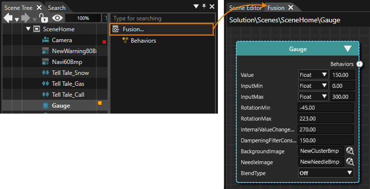
- In Fusion drag the Fusion node's Behaviors connector to the right and release the mouse button.
- The Select Behavior dialog will be opened displaying a list of behaviors.
- The list of behaviors is organized similar to the behaviors in the Toolbox.
- There is an input field just above the behaviors list.
- Click into the Select Behavior's input field and start typing "Forward Value".
- While typing the list of behaviors will be filtered so you can easier find the desired behavior.
- Double-click the "Forward-Value" behavior.
- The Select Behavior dialog will be closed.
- Fusion has added a Forward Value node to its diagram.
- This behavior is responsible for copying the speed value from the Gauge control to the TextValue control.
- Configure a TargetNode for the Forward Value behavior, so it knows, where it should forward the value to. Click on the magnifying glass in the Forward Value Fusion Node.
- The Choose Item dialog will be opened.
- Navigate to the Text Value control, select it and click [ OK ].
- The Text Value control is selected as TargetNode for the Forward Value behavior.
Item Name TargetNode Forward Value Scenes/SceneHome/CompositeNode2D:Text Value
- The Text Value control is selected as TargetNode for the Forward Value behavior.
Add a FlipBook
The top center of our home screen is decorated with a "DigitalClock" control. We will also add a "FlipBook" control to the upper right corner of the scene.
- Drag and drop a DigitalClock control from the ToolBox (under [ Controls ] - [ Common ]) to the Scene Editor.
- A DigitalClock control will be placed into the scene.
- Configure its Position properties in the Properties panel's [ Transformation ] section.
- The DigitalClock control will be positioned as configured.
Item Name Position X Position Y DigitalClock 439 116
- The DigitalClock control will be positioned as configured.
- Drag and drop a FlipBook from the ToolBox (under [ Controls ] - [ Common ]) to the Scene Editor. Place it in the upper right corner.
- A FlipBook control will be placed into the scene.
- Configure its properties in the Properties panel's [ Transformation ] section.
- The FlipBook control will be positioned as configured.
Item Name Position X Position Y Scale X Scale Y FlipBook 745 121 0.50 0.50
- The FlipBook control will be positioned as configured.
Check the First Scene
The first screen/scene is now finished.
- To check the result of configuring the first scene, open the display view. This view represents the final rendered result and can be opened via the menu bar: View - Display - Display-0.
- The display panel will be opened in a floating way displaying the scene configured in the steps above.

- The display panel will be opened in a floating way displaying the scene configured in the steps above.
- In the Toolbar make sure that the item "Generate and Play" is selected in the drop-down menu and click the [ > ] button to the left.
- This will generate the asset so it is available as input for the Player. After that the CGI Panel will be started.

- This will generate the asset so it is available as input for the Player. After that the CGI Panel will be started.
- In the CGI Panel select "Scenes#SceneHome" on the left and click on the [ Controls ] tab.
- All of the scene's controls are listed.
- Select the Gauge control.
- The Gauge control's properties are displayed in a table on the right.
- To check the functionality of the configured ForwardValue behavior click in the table's field of the property "Value" and manipulate its "Value" to e.g. 35.
- The Gauge's needle will adjust its rotation to display 35.
- The TextValue control will also update its value to 35.

- The Gauge's needle will adjust its rotation to display 35.