
Creating a 3D Font for CGI Studio
The scope of this section is providing step-by-step instructions for creating a 3D font which can be used within the CGI Studio tool chain.
Overview
Any TrueType font can easily be adapted for use within the CGI tool chain. All needed is an FBX file containing a set of meshes which represent the 3D letters of the font. The name of each character mesh within the set must end with a four-digit code, the so called “code point”, which identifies a character in Unicode space.
All character meshes within the set must be aligned at the same baseline and at their left ends, resulting in a 3D scene with all character meshes being stacked on top of each other.
A single helper object, a “dummy” in 3ds max, is placed at the left end and baseline of the meshes. It not only serves as the root object within the scene hierarchy but will also become the anchor point, a kind of “physical” pivot, for character manipulation (moving, rotating, resizing) within CGI font widgets at a later step.
Creating a 3D Font in 3ds Max 2023
Get Name Suffix for the Character Mesh
For being automatically identified within CGI Studio the name of each character’s mesh must end with the four digits Unicode code point. If working in Windows, you can find this hex value using the Charmap (Windows -> Start -> Run… “Charmap”). Just select a letter and look up its four-digit code point in the bottom left corner.
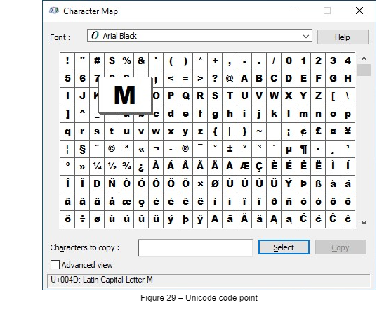
In Figure 29, the value of the selected letter “M” is “004D”.
The code points may also be found on the Internet (e.g.: http://www.utf8-chartable.de/).
Create First Character
- Start 3ds Max.
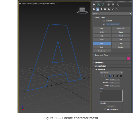
- Create -> Shapes -> Text
Choose desired font (in our example “Arial Black”), set Size to e.g., 100, type a character into the text field (e.g. “A”) and then, preferably in the “Front” viewport, place the character on the grid. - Give the mesh a meaningful name (without using special characters or spaces) and as suffix add the Unicode code point explained in chapter Get Name Suffix for the Character Mesh. Valid names would be “Letter_A_0041”, “PlusSign002B” or just “007A”.
- Finally set the mesh position to 0,0,0.
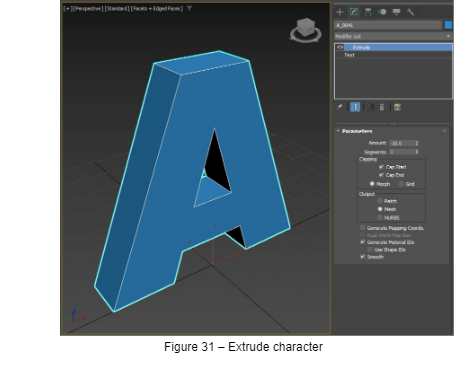
Extrude Character
Modifiers -> Mesh Editing -> Extrude -> Set “Amount” to e.g., “-10”.
Clone and Create Remaining Characters
- Select the character mesh -> Edit -> Clone
- Set “Object” to “Copy” and enter a name for the new character.
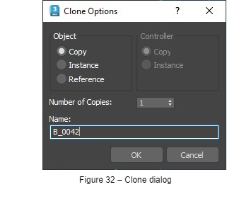
- Go to the Modify panel -> select the “Text” object -> replace the character in the text field with new one. You should now see two overlapping character meshes in your viewport.
- Repeat until all needed characters are created.
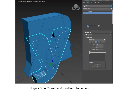
Anchor Object
Currently the pivot point of each mesh is set to 0,0,0 – therefore positioned at each character’s Z-baseline Y-front and X-center (given that Z is the up axis in the scene).
However, for usage within CGI Studio we need an anchor at the left side of the characters and at the center of their Y (depth) dimension. Moving the pivot point won’t serve that purpose because pivot settings will be ignored later in the tool chain. So, we have to introduce a dummy which will become the root object of all character meshes and will serve as pivot or anchor point for object manipulation within CGI Studio.
Align the Character Meshes
To ease the process, we first align all character meshes along their left minimum:
-
- Select all character meshes -> Tools -> Align -> Align… -> Edit -> Select by -> Name
- While the align cursor still is visible select any character mesh in the “Pick Object” dialog and press “Pick”.
- In the “Align Selection” dialog remove all checkmarks except for “X Position”. Set “Current Object” and “Target Object” to “Minimum” and press “Apply”.
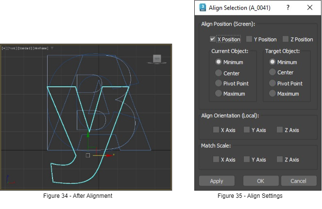
- Select all character meshes -> Tools -> Align -> Align… -> Edit -> Select by -> Name
Anchor Creation and Positioning
-
- Create -> Helpers -> Dummy
Drag the mouse inside the viewport until a rectangle – or in perspective view a cube – becomes visible. Tipp: Always keep dummies very small in relation to the meshes to prevent their bounding boxes from cluttering the viewport later on. - Assign some meaningful name to the dummy, e.g., in our case the font name: “Arial_Black”.
- Set the dummy’s Z position to “0”, so its pivot is aligned with the character baseline.
- For aligning X and Y we again need the align tool. Select the dummy and as learned in 5.2.5.1, pick any character mesh as target object.
- Create -> Helpers -> Dummy
-
- In the “Align Selection” dialog again remove all checkmarks except “X Position” but this time as “Current Object” set “Pivot Point”, as shown in Figure 36. “Target Object” again is “Minimum”. Click “Apply” to leave the dialog open after X alignment.
- Now remove the “X Position” checkmark and check “Y Position”. Change “Target Object” to “Center” and click “OK”. (Note: If Y is your up axis you might have to align along Z instead of Y.)
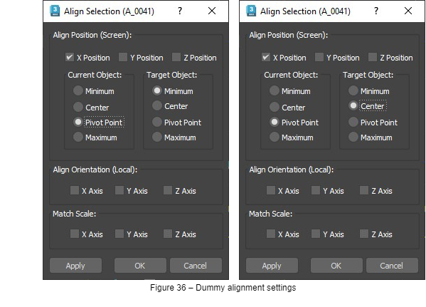
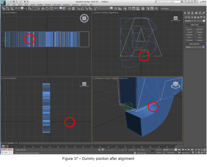
- In the “Align Selection” dialog again remove all checkmarks except “X Position” but this time as “Current Object” set “Pivot Point”, as shown in Figure 36. “Target Object” again is “Minimum”. Click “Apply” to leave the dialog open after X alignment.
Create Object Hierarchy
-
- Go to Tools -> Open Explorer: Container Explorer
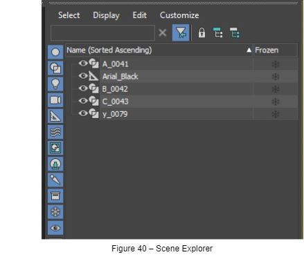
- Disable display of helpers via toolbar button (or Display -> Object Types -> Display Helpers).
- Select all objects (Ctrl + A) and re-enable display of helpers.
- Now move the mouse to the yellow highlighted line -> drag the icon at the left -> drop it in the line of the dummy helper object . After this step the explorer view should look similar to Figure 38.
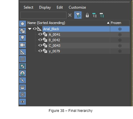
- Go to Tools -> Open Explorer: Container Explorer
Export as FBX
The final step is to export the scene as FBX. Please ensure that in the FBX export dialog “Y-up” is set as “Up Axis”.