
CGI Studio Smart Importer
Overview
Use the Smart Importer to quickly and easily import digital assets to your solution. With AI assistance you can assign functional HMI controls to elements within your design in a straightforward manner. Several other useful features are included, such as layer merging or multiple scene support.
With the Smart Importer you can import Photoshop files or files in Candera’s “XML Scene Composer Intermediate Format” (xscil) into your Scene Composer solution.
The Smart Importer uses Artificial Intelligence (AI) to analyze the content of the imported PSD or XSCIL file.
How to Use the Smart Importer
Select File for Smart Importer
The Smart Importer will analyze imported files with the assistance of AI to detect, propose and create controls for your Scene Composer solution. Use the Import > Smart Importer… option from the menu bar to open the dialog box for the Smart Importer.
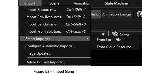
After choosing “Smart Importer” from the menu, choose your import location.
Importing "From Local File..." will open the Windows "Open" dialog box, allowing to select the following file types:
- *.psd
- *.xscil
- *.xd
- *.rp
- *.sketch
Smart Importer Windows
Once you have selected a file to import, the Smart Importer window will be opened.
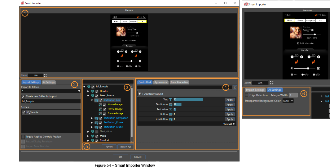
The Smart Importer window consists of the following panels:
| (1) | Preview |
The preview panel displays a preview of the graphics file o be imported. You can use the mouse wheel to zoom in and out, with the zoom percentage displayed in the lower left corner of the preview panel. By pressing the button displaying four arrows, you can modify the preview image’s size within the panel’s maximum available space. |
| (2) | Import Settings |
The import settings panel will allow you to select a destination folder to import template solutions. You can choose to create a custom imports folder, which will be created inside the destination folder. |
| (3) | Layer Tree |
The layer tree panel will display the elements imported from your graphic file as a branching list. The list displayed within this panel is equivalent to the template scene’s Scene Tree within Scene Composer. You can select one or multiple items within this list to begin the AI detection process. The filter bar located on top of the layer tree will allow you to more easily identify a specific layer when dealing with multiple layers. |
| (4) | Control List, Appearance and Basic Properties |
By selecting a layer, the AI will attempt to detect which controls are suitable for the selected elements. The result of this analysis will be displayed in the ControlList panel, listing the candidate control from greatest to least probability. The list of controls can also be filtered using the input field on the top. Use the “Apply” button in the control list to apply a control to the selected element. If the AI has detected only a weak probability for your selected control, you will be prompted to confirm your choice. |
| (5) | Revert & Revert All |
You can select an item in the layer tree panel (3) and revert the already applied control using the “Revert” button. You can choose to revert all applied controls in the “Layer Tree” by pressing the Revert All button. You will be prompted to confirm this action in order to keep you safe. |
| (6) | AI Settings |
In the AI Settings you can change the Transparent Background Color for AI detection. The selected color is used by the AI to analyze the graphics to be improved. It pretty much depends on the content of the image, which transparent background color works best for detecting controls. IN case the AI is having problems in detection controls, you can try to change this setting. |
Configure Scenes
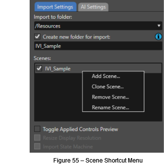
In the Import Settings Panel you can manage the scenes you want to import into Scene Composer. Opening the shortcut menu, you will see the available options: Add Scene, Close Scene, Remove Scene, and Rename Scene. Double-clicking on the scene’s name allows you to rename an existing scene.
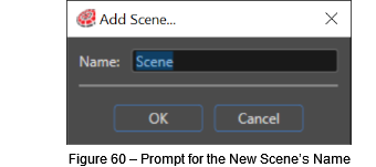
If you choose to add a new scene or clone the existing scene, you will be prompted to input the name for the new scene.
The AddScene and Remove Scene options will be disabled when multiple scenes are included within the imported Intermediate Language file.
Configure the Scene’s Content
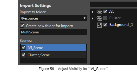
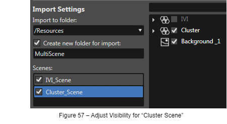
Let’s assume you got a graphic file from your designer with 2 scenes, an IVI scene (e.g. with a music player and climate control) and a Cluster scene. You will create two scenes in the Import Settings panel: an “IVI_Scene” and a “Cluster_Scene”. Select the “IVI_Scene” and adjust the visibility of the layers in the Layer Tree panel – only “IVI” and “Background_1” will be checked. Handle the “Cluster Scene” similarly – only “Cluster” and “Background_1” will be checked.
Clus
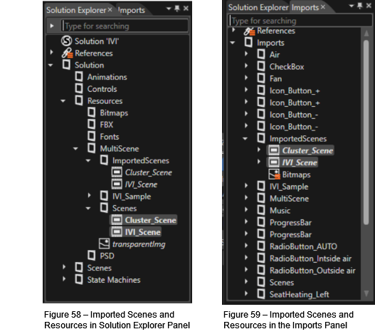
When clicking the OK button, the import is started. You can then see the imported scenes and resources in the Solution Explorer panel and in the Imports panel of Scene Composer.
Detection, Configuration and Import of a GaugeControl
When you import a graphics file that includes a gauge using the Smart Importer the AI will detect this control and import the template scene including the correctly identified gauge control-
To make the AI detect the gauge in your graphics file, open the graphics file with the Smart Importer (via the Menu: Import – Smart Importer and choose your graphics file). Your graphics file will be displayed in the “Preview” panel.
Now you can select your gauge by clicking on the corresponding graphics in the “Preview” panel. The Layer Tree panel will expand the layers and mark the layer you selected.
As an alternative, you can browse to the desired layer in the “Layer Tree” panel. If you know at least part the layer’s name, you may use the filter field in the top of the Layer Tree panel to find the correct layer more easily. The content you select in the “Layer Tree” panel will be highlighted with a yellow frame in the “Preview” panel.
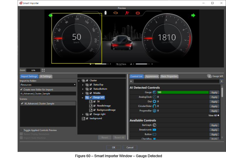
Whenever you select any content – no matter if selecting single layers or multiple layers – the AI tries to detect known controls. You can see the list of detected controls in the “Control List” panel on the bottom right.
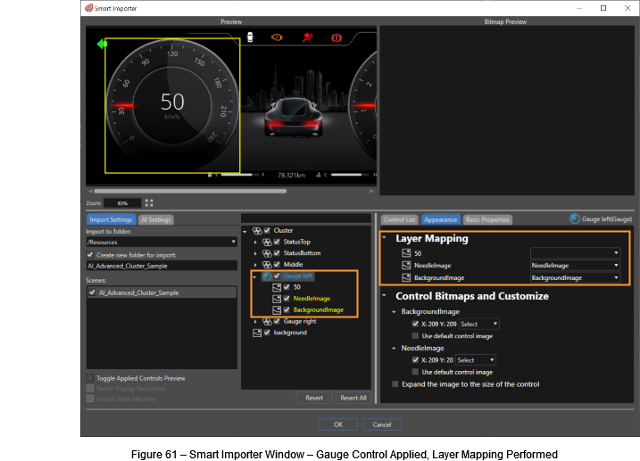
In our example the AI correctly detected a Gauge Control, so you will press the “Apply” button on the right. The Appearance Tab is put to the foreground, offering you the possibility to configure the GaugeControl’s NeedleImage and BackgroundImage. After performing this Layer Mapping, you will see the GaugeControl Layer in the “Layer Tree” panel and its content will be colored, indicating a successful application of the GaugeControl (blue font) and a successful mapping of the image (yellow font).
Configure the Pivot Point
For all images configured in the Layer Mapping, you can configure the pivot point in the Appearance Tab on the bottom right. In our example for the GaugeControl it is important that the pivot point of the needle image is set correctly in order to guarantee the correct movement of the needle in Scene Composer.
There are 3 ways to configure the pivot point:
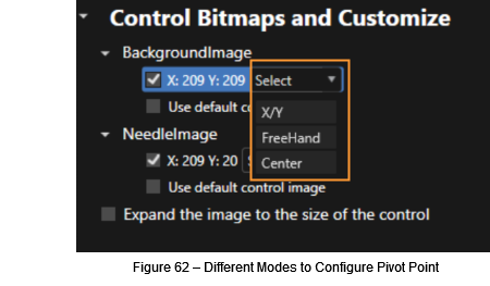
- Enter digits for the X/Y coordinate.
- Freehand position a crosshair cursor using the mouse.
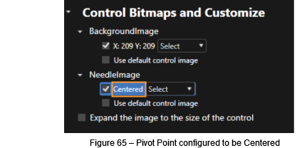
- Configure the pivot point to be in the center of the image.
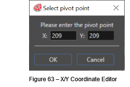
- X/Y: You can choose this option to enter the X/Y coordinates for the pivot point in the following editor.
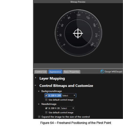
- Freehand: If you choose this option, you can move the crosshair cursor to the desired pivot point in the “Bitmap Preview” panel.
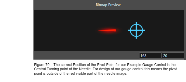
- Center: With this option, the pivot point will be configured to the center of the image. A center configuration of the pivot point will be indicated by the text “centered” in the Appearance tab.
Configure Basic Properties
The controls have been detected by the AI and you have applied them to your layers. In the appearance tab you have mapped your layers to images that are part of the controls (i.e. the gauge’s needle image and the background image). You can also define values for basic properties of the applied control.
The following basic properties are available for the gauge control. To easily find our gauge control instance in Scene Composer after the import, you may also change its name to e.g. “Gauge_for_speed”.
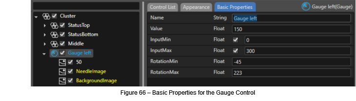
Individual properties from your design will be automatically mapped if the property’s name is the same as the control’s property name.
Import to Scene Composer
Once you are finished applying the detected controls and configuring images, pivot points and other properties, click the OK button to import your configured file.
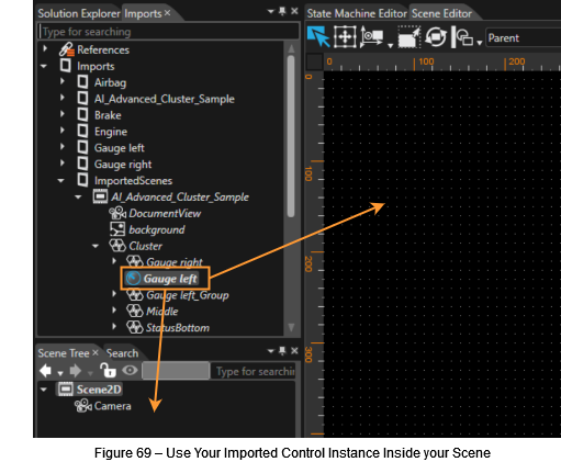
You can now see that the folder “AI_Advanced_Cluster_Sample§ has been created and the content of your psd file has been imported. The gauge control instance “Gauge_for_speed” you configured using the Smart Importer can be found in the “Imports” panel.
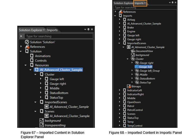
You may create an instance of your “Gauge_for_speed” by dragging it into your scene – either into the Scene Editor panel or into the Scene Tree panel.
7.3.5. Layer Merging
Sometimes the graphics file to import will be quite complex, having several images for a gauge’s background and a few images for a gauge’s needle to achieve a brilliant HMI. The built in GaugeControl of Scene Composer however requires only one image for the background and one image for the needle. To meet the needs of both, complex graphics files and a clear implementation and configuration of the control, the Smart Importer is able to configure several layers for a single image of the control.
In the following example the layers for the gauge’s background are marked in orange and the layers for the needle are marked in red.
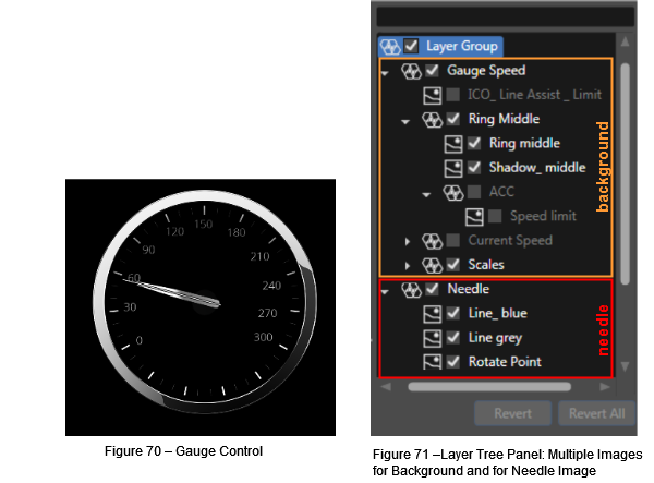
Select the root of the gauge in the “Layer Tree” panel that includes both the background images and the needle images. In our example this layer is called “LayerGroup”. In the “Control List” panel you will see that the AI has detected the GaugeControl. After pressing the “Apply” button next to the GaugeControl you can map the layers to the GaugeControl’s background and needle image.
Useful Hints:
- You can configure a complex layer group by selecting and configuring only the root. All its children will be configured similarly.
- You can select multiple layers and configure them all at once. For multi selection you can keep the <ctrl> or <shift> key pressed while selecting the layers with a mouse click or you can click-and-drag a box around the layers you want to select.
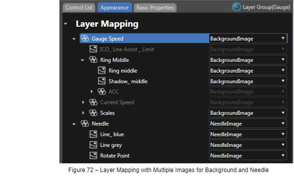
Finalize the configuzration of your GaugeControl by setting the NeedleImage’s pivot point to exactly that point where the needle should rotate around as described in Configure the Pivot Point.
After the configuration is complete you can press the “OK” Button of the Smart Importer to import your graphics file and the configured GaugeControl Instance into SceneComposer.
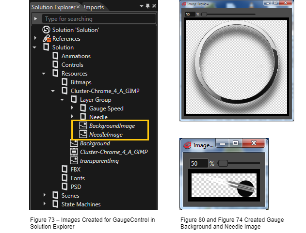
Smart Importer has created a single image for the needle and a single image for the background as you can see in the Solution Explorer.
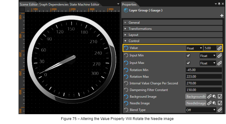
To test the functionality of the GaugeControl, drag and drop the configured GaugeControl instance to the scene (as described in Import to Scene Composer). When altering the GaugeControl’s value in the Properties panel, the needle of the GaugeControl in the Scene Editor panel will rotate in front of the background according to the alteration of the Control’s value.
Re-Importing of Graphics Content
When importing the same content to the same location once again, the resources and scenes in Scene Composer are overwritten. This allows you to replace outdated graphics of your scene with newly updated graphics from your designer while maintaining the mapping between layers and controls.
Reload Configuration for New Graphics File
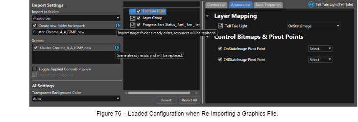
If you use the Smart Importer to open the same graphics file (same path, same filename) again, which you have already made configurations to, you will see your configurations are available again (marked with orange font in the layer tree panel). The applied controls as well as the Layer Mapping have been loaded.
You will be notified by blue information icons that the import target folder or the scene already exist (A tooltip gives you the necessary information once you hover those icons). Starting the import as currently configured will overwrite already imported resources and scenes and therefore update the graphics of your Scene Composer solution to the newest graphics version, while keeping the information of mapped layers and applied controls.
If you want to import graphics content to your Scene Composer solution for a second time, maintaining the resources and scenes from both imports, you can choose a different import location or a different scene name.
Re-Import of a Graphics File with Different Layers
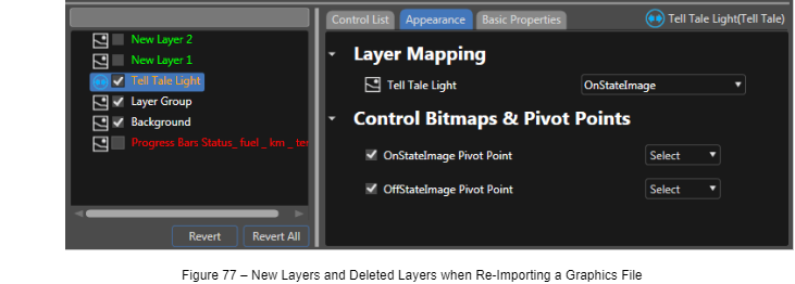
When importing a graphics file with the same path and filename but partially different layers, you will see the configuration of the layers that are still available has been loaded.
- The orange font indicates that a bitmap from the node assigned to the control is currently in use within another control.
- Layers that had not been part of the graphics file before will be displayed in green font. They are not visible in the preview panel since they are disabled by the layer tree panel’s checkbox.
- Layers that are missing in the currently loaded file are displayed in red font in the layer tree panel. The content of layers that are not available in the currently loaded graphics file cannot be displayed since the image data is simply missing. Checking the checkbox in the layer tree panel won’t make any change in the preview panel.
Restore a Configuration
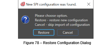
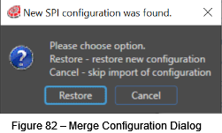
If you have already imported a graphics file into a certain folder and you are attempting to import the same graphics file to the same folder again, the Smart Importer will load the configuration you applied last time. If you are reverting your configuration using the Revert All button, the loaded configuration is gone. However, the configuration of the last successful import is still saved with the lastly imported scene. So, changing the import location and changing it back to the original import location, where the configuration is saved, makes a dialog pop up asking you whether you want to restore the saved configuration.
Choose Restore to restore the configuration from your last import or Cancel to start configuring all over again.
Merge Configurations
A configuration that has been imported to Scene Composer is saved to the imported scene. You can use one graphics file, import various configurations to Scene Composer and merge them together into one final configuration.
I. Create Configurations
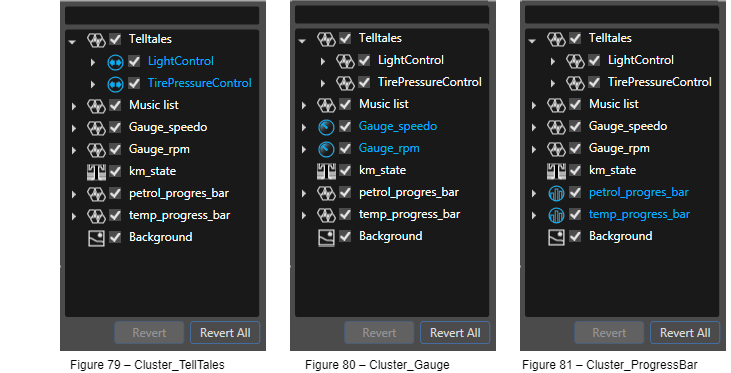
- Open your Cluster graphics file using the Smart Importer, configure the Telltale controls and import them to folder Cluster_Telltales for example.
- Open the graphics file again and configure the Gauge Controls; import them to folder Cluster_Gauge.
- Once again open the graphics file and configure the ProgressBar Controls; import them to folder Cluster_ProgressBar.
II. Merge Configurations
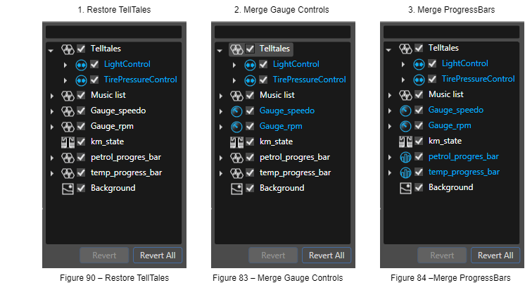
- If you now open the Cluster graphics file again and set the import folder to Cluster_Telltale you can restore the configuration for your Telltale controls by clicking Restore in the Restore a Configuration dialog.
- Now, change the import folder to Cluster_Gauge, which triggers the following dialog, where you choose Merge to add the Gauge configuration to the currently loaded Telltale configuration.
- Change the import folder to Cluster_Progressbar and merge the configuration of the progressbars to your currently loaded and merged configurations.
And finally, you’ll end up with a configuration having applied TellTale Controls, Gauge Controls and ProgressBar Controls.
Advanced Configuration of PSD Content for Import to Scene Composer
Import Bitmap Resources
Images of Image Layers in psd data are imported as Bitmap Resources. By default, the value of the Pivot Hint of imported Bitmap Resources is calculated to be in the center as follows:
Pivot Hint X = Image Layer width /2
Pivot Hint Y = Image Layer height /2
You can set the Pivot Hint in Photoshop by embedding the token into the layer’s name. The Pivot Hint tokens are removed from the Bitmap Resource name upon import.
E.g. 1: If the layer’s name in the photoshop file is "Image@X30.5@Y40"
the Bitmap resource name will be “Image”,
Pivot Hint X = 30.50
Pivot Hint Y = 40.00
E.g. 2: If the layer’s name in the photoshop file is "ImageData@Y40.55"
the Bitmap resource name will be “ImageData”,
Pivot Hint X = "ImageData@Y40.5" layer width / 2
Pivot Hint Y = 40.55
TextStyle
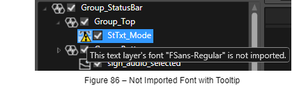
When importing a Text Layer into Scene Composer, a new TextStyle is created. Its name will be a combination of the font name and the font size used in the Text Layer of the PSD file. Upon creation of a new TextStyle Scene Composer checks if a font resource with the corresponding name is registered in the Scene Composer solution. In case no suitable font resource has been found in the solution, a new TextStyle will be created using the font resources displayed in the “Not imported font” dialog.
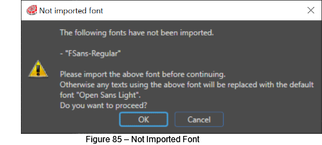
Fonts that are not imported are also marked with a warning sign in the “Layer Tree” panel. A tooltip offers additional information:
Technical Details
Collaboration of Scene Composer, ControlsAIService and ControlsAIApp
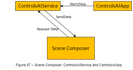
Scene Composer comes with two additional applications that are needed to make the AI detection work:
- ControlsAIService: A windows service application that provides the AI data for Scene Composer.
- ControlsAIApp: A tray icon application that controls the service.
The following diagram explains the collaboration of the Scene Composer, the ControlsAIService and the ControlsAIApp:
XML Scene Composer Intermediate Format – XSCIL
XML Scene Composer Intermediate Format (XSCIL) is an open and well-defined format which has been invented to export graphics data from various user experience design tools (Axure RP, Adobe XY, Sketch etc.) and import them into Scene Composer via the Smart Importer. An API is available which you can use to implement an exporter for your favorite graphics editor, if it isn’t already available.
Recommended Photoshop (.PSD) Layer Structure for Smart Importer
These are the recommended steps for Photoshop layers’ naming and structure of a Control when creating a PSD file with Adobe Photoshop. Tis procedure makes it easier to apply properties to a Control via the Smart Importer.
- Create a group for the target Control – in this case, a TextButton (blue highlight in Figure below)
- Create layers for the properties of the Control under the group created in step 1. (red and green highlight in Figure 88 below)
- Set the names of the layers to be the same as the property names of the target Control. (layers names in Figure 88 below correspond to property names in Figure 89)
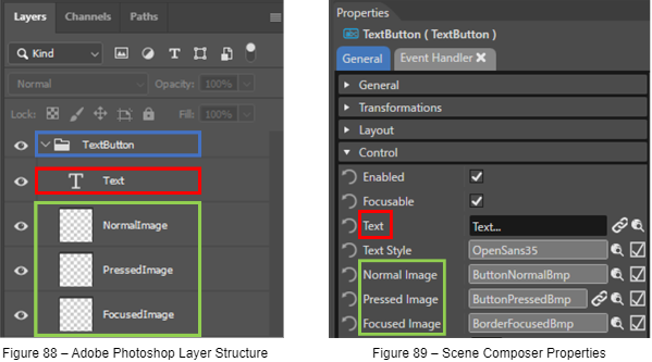
How to set appropriate group and layer names:
- The group name is arbitrary.
- For the layer name, use the property name but remove the spaces. For example, “Normal Image” becomes “NormalImage”.
Figure 90 shows the Smart Importer dialog when a PSD file following the correct format is opened.
It is imported according to the layer structure of the PSD file.
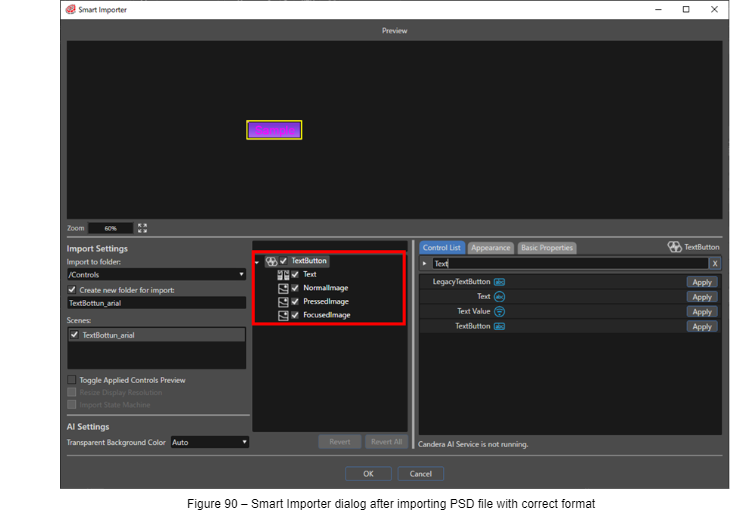
In the Smart Importer dialog, if you apply the TextButton control to the TextButton node, the layers of the PSD file will be reflected in each property as shown in Figure 91.
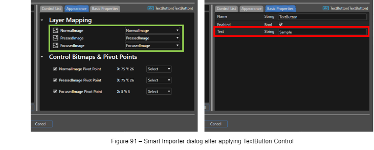
Figure shows the Properties panel after import settings shown in Figure 91. The contents/layers of the PSD file are reflexted in the Properties panel.
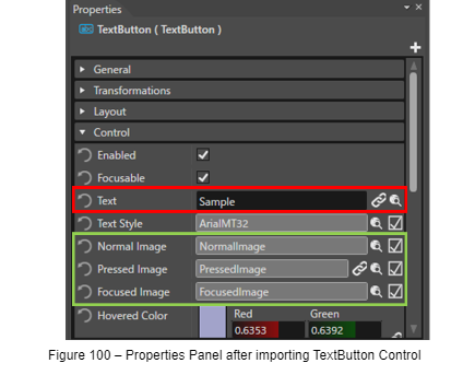
The size of the imported Control will be adjusted to the Width and Height of the largest image layer applied to a property.
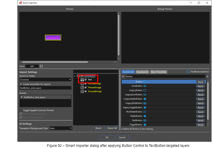
In Figure 92, when Button is applied instead of TextButton, Text property is not applied correctly since a Button control does not have this property.
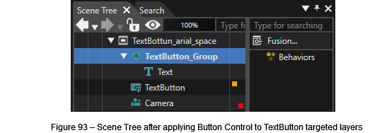
If you import a node whose layers and properties do not match, a new Group node will be created and the extra property is added as its child element.
7.5.1. Layer Structure and Naming Guideline for Controls
In general, it is recommended to keep the PSD layer format close to the standard Controls. Below is a guide on how the layers for some Controls should be formatted and named.
| AnalogClock | Breadcrumb | CheckBox |
|
|
|
| CircularSlider | Gauge | GroupBox |
|
|
|
| IconButton | InputField | Menu Icon |
|
|
|
| Menu Item | Menu Screen | Mesh2D |
|
|
|
| MultiStateButton | PageIndicator | RadioButton |
|
|
|
| Roll | SpinBox | TextButton |
|
|
|
| ToggleButton | TouchIndication | |
|
|