
Part 2: Configuring State Machine
This page explains the steps for building state transitions (state machines) between multiple scenes in CGI Studio.
It begins by recreating the Global State Machine for the scenes created in Part 1 and configuring state transitions for Main Menu, Navigation, Phone, Media Menu, and other scenes. Each state uses OnEntry/OnExit actions to control scene activation and deactivation, as well as the rendering of related text nodes. It also covers setting screen transitions using left and right key inputs (Key_RightArrow/Key_LeftArrow), configuring transitions using Fusion nodes, and defining transition conditions for each scene. Finally, transition behavior is verified using the Player.
Creating a new State Machine
The solution created in Part 1 (created based on the Empty solution) includes a GlobalStateMachine by default. In this part, we will delete this existing Global State Machine and create a new State Machine to deepen our understanding of custom settings.
Deleting the existing Global State Machine
- Select the GlobalStateMachine in the [ State Machines ] folder in the Solution Explorer, and then select [ Delete ] from the context menu.
- The [ Delete Items ] dialog will appear.
- Click the [ OK ] button in the dialog to delete the item.
Creating a new State Machine
- Select [ State Machines > New State Machine ] from the menu bar.
- The [ New State Machine ] dialog will appear.
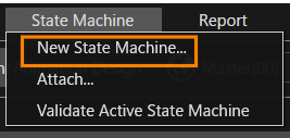
- The [ New State Machine ] dialog will appear.
- Click [ Browse ] at the top of the dialog.
- The [ Select Location ] dialog will appear.
- The [ Select Location ] dialog will appear.
- Select StateMachines and click [ OK ].
- The location “/State Machines” is selected as the save location for the new State Machine.
- Set [ Name ] in the dialog to "Main_StateMachine" and click the [ OK ] button.
- The Main_StateMachine is newly created in the [ State Machines ] folder in the Solution Explorer.
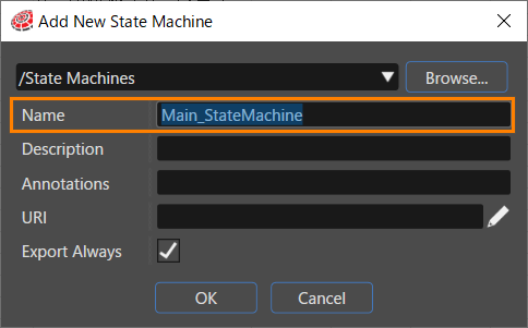
- The Main_StateMachine is newly created in the [ State Machines ] folder in the Solution Explorer.
Setting the Global State Machine
- Select the Main_StateMachine in the [ State Machines ] folder in the Solution Explorer.
- The Main_StateMachine properties will be displayed in the Properties panel.
- Enable the [ Is Global ] checkbox in the [ General ] category of the properties.
- The Main_StateMachine will be set as a Global State Machine.
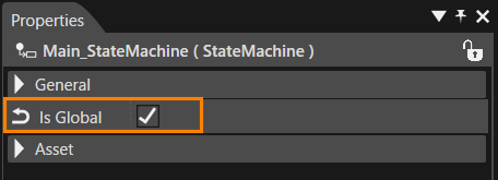
- The Main_StateMachine will be set as a Global State Machine.
For details on the functions of the Global State Machine, please refer to this page.
Basic Structure
Using the Main_StateMachine we created earlier, we will add a State to configure the initial state of the Main Menu scene, and then set the appropriate rendering settings. In addition, when the Main Menu State is entered, the Main Menu scene will be activated, and the Clear and Swap scenes will also be activated so that they are rendered correctly.
Initial State and State Addition for Main Menu
- Double-click on the Main_StateMachine in the [ State Machines ] folder in the Solution Explorer.
- The State Machine Editor panel will be displayed.
- There is already an Initial State and one State.
- Select the State on the State Machine Editor.
- The properties of the selected State will be displayed in the Properties Panel.
- Change the [ Name ] in the [ General ] category of the Properties Panel to MainMenu.
- The State name on the State Machine Editor will change to MainMenu.
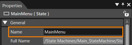
- The State name on the State Machine Editor will change to MainMenu.
Adding an OnEntry Action
- With the MainMenu State selected, click [ Fusion ] at the bottom left of the State Machine Editor panel.
- The Fusion panel for the MainMenu State will be displayed.
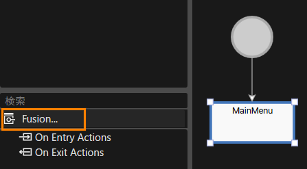
- The Fusion panel for the MainMenu State will be displayed.
- Drag the [ On Entry Actions ] connector on the right of the MainMenu Fusion node and move the mouse.
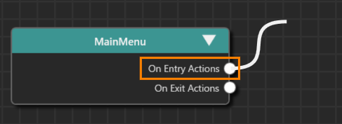
- A link will appear as you move the mouse, so release the left mouse button at the any location.
- The [ Select Behavior ] dialog will be displayed.
- The selectable behaviors will be displayed by category.
- Select “Action > Transition > Transition Request” from the list and connect it to the top node.
- You can also narrow down the list of behaviors in the dialog by entering “Transition Request” in the search field at the top of the dialog.
- Transition Request is connected to MainMenu.
- The default Activate is selected for the [RequestType] of Transition Request.
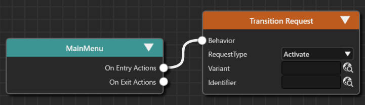
- Press the select item button to the right of the [ Identifier ] of the Transition Request.
- The [ Choose Item ] dialog box will appear.
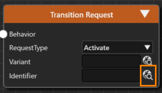
- The [ Choose Item ] dialog box will appear.
- Select [ Scenes > Main Menu ] from the left window.
- The Main Menu you selected will be registered in the [ Identifier ] of the Transition Request.
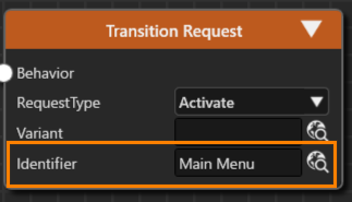
- The Main Menu you selected will be registered in the [ Identifier ] of the Transition Request.
- Select the Transition Request Fusion node you set up, and execute [ Close ] from the context menu.
- On the [ Clone Item ] dialog, select the [ Multiple Clone ] tab, specify 2 for [ Number of Copies ] and click the [ OK ] button.
- The duplicated Fusion nodes overlap, so move them using the mouse.
- The Fusion nodes named Transition Request_1 and Transition Request_2 are connected to the MainMenu Fusion node.
- The [ RequestType ] of each Fusion node is set to the default Activate.
- For the [ Identifier ] of the added Transition Request Fusion nodes, select the Swap and Clear scenes respectively.
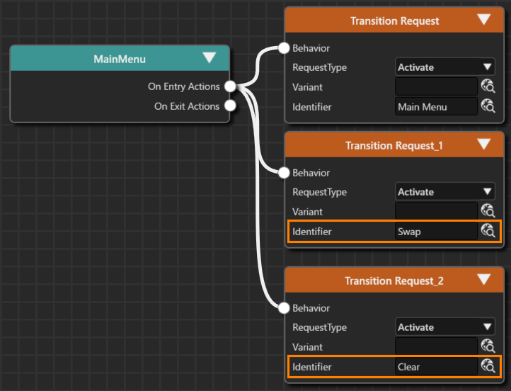
This completes the settings for the OnEntry action for the MainMenu State. When you transition to the MainMenu State, the Clear and Swap scenes will be activated in addition to the Main Menu scene, so things like clearing the render will be executed at the same time.
Main Menu State Structure
Adding a State
- Double-click on Main_StateMachine in the [ State Machines ] folder in the Solution Explorer.
- The State Machine Editor will appear.
- After selecting the MainMenu State, drag the resizing handles displayed in the four corners of the state with the mouse to expand the size of the MainMenu State.
- Place one Initial State and three States in the MainMenu State from the toolbar at the top right of the State Machine Editor.
- Change the names of the three added States to Navigation, Phone and Media respectively.
- For instructions on how to change State names, please refer to here.
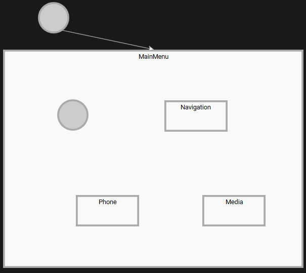
- For instructions on how to change State names, please refer to here.
OnEntry/OnExit settings
When transitioning to each State (entering and exiting States), it is necessary to activate and deactivate the corresponding scenes. In addition, when each scene is activated or deactivated, it is necessary to set the Main Menu scene text to be displayed or hidden in conjunction with this.
Scene display settings
- With the Navigation State selected, click [ Fusion ] in the lower left of the State Machine Editor panel.
- The Fusion panel for the Navigation State will be displayed.
- Drag the [ On Entry Actions ] connector on the right of the Navigation Fusion node and move the mouse.
- A link will appear as you move the mouse, so release the left mouse button at the any location.
- The [ Select Behavior ] dialog will be displayed.
- The selectable behaviors will be displayed by category.
- Select “Action > Transition > Transition Request” from the list and connect it to the top node.
- You can also narrow down the list of behaviors in the dialog by entering “Transition Request” in the search field at the top of the dialog.
- The Transition Request is connected to [Navigation > On Exit Actions].
- Repeat the same process for the [On Exit Actions] of the Navigation Fusion node to connect the Transition Request Fusion node.
- Make the following settings for the two Transition Requests that you have connected.
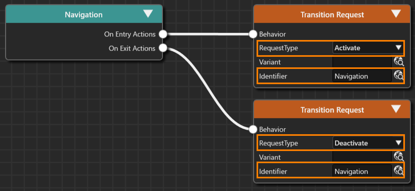
On Entry Actions RequestType Activate Identifier Navigation On Exit Actions RequestType Deactivate Identifier Navigation - Repeat the same procedure to make similar settings for Phone and Media State.
Phone State On Entry Actions RequestType Activate Identifier Phone On Exit Actions RequestType Deactivate Identifier Phone Media State On Entry Actions RequestType Activate Identifier Media Menu On Exit Actions RequestType Deactivate Identifier Media Menu
Text Display Settings
- With the Navigation State selected, click [ Fusion ] at the bottom left of the State Machine Editor panel.
- The Fusion panel for the Navigation State will be displayed.
- Drag the [ On Entry Actions ] connector on the right of the Navigation Fusion node and move the mouse.
- A link will appear as you move the mouse, so release the left mouse button at the any location.
- The 'Select Behavior' dialog will appear.
- The available behaviors will be displayed in categories.
- Select "Action > Property > Enable Rendering" from the list and connect it to the top node.
- You can also narrow down the list of behaviors in the dialog by entering "Enable Rendering" in the search field at the top of the dialog.
- Enable Rendering is connected to [Navigation > On Exit Actions].
- You can also narrow down the list of behaviors in the dialog by entering "Enable Rendering" in the search field at the top of the dialog.
- Repeat the same process for the [On Exit Actions] of the Navigation Fusion node to connect the Enable Rendering Fusion node.
- Make the following settings for the two Enable Renderings that have been connected.
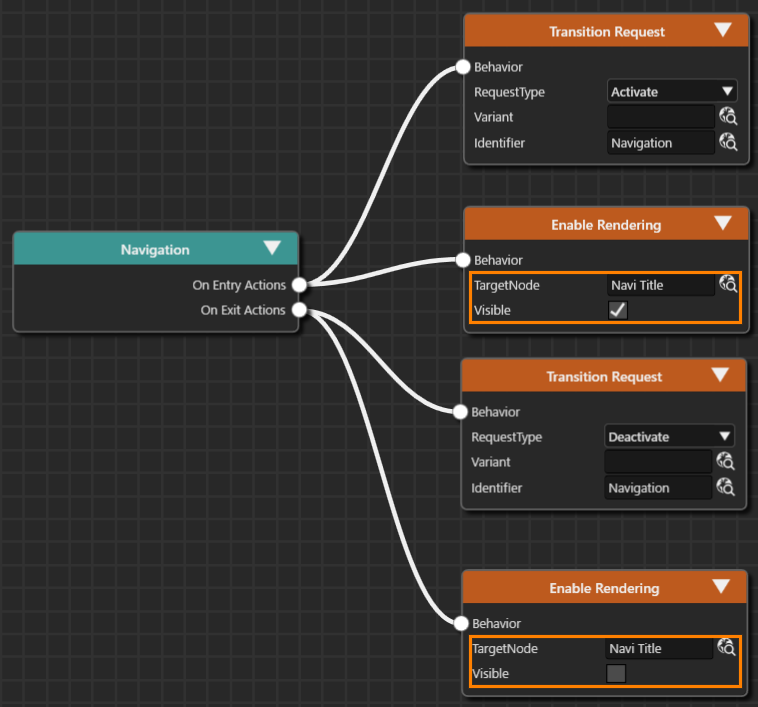
On Entry Actions TargetNode Scenes>Main Menu>OverlayLayout>Navi Title Visible Enable (check box selected) On Exit Actions TargetNode Scenes>Main Menu>OverlayLayout>Navi Title Visible Disable (uncheck) - Follow the same procedure to make similar settings for Phone State and Media State.
Phone State On Entry Actions TargetNode Scenes>Main Menu>OverlayLayout>Phone Title Visible Enable On Exit Actions TargetNode Scenes>Main Menu>OverlayLayout>Phone Title Visible Disable Media State On Entry Actions TargetNode Scenes>Main Menu>OverlayLayout>Media Title Visible Enable On Exit Actions TargetNode Scenes>Main Menu>OverlayLayout>Media Title Visible Disable
Adding a Transition
We will now create a transition between the states we have created so far.
Setting the Initial State
We will set the transition from the Initial State to the Navigation State, which is the initial state.
- Double-click on Main_StateMachine in the [ State Machines ] folder in the Solution Explorer.
- The State Machine Editor will appear.
- Drag and drop [ Transition ] from the toolbar at the top of the panel to the Initial State in the MaiMenu State.
- The Transition will be connected to the Initial State, and it will be ready to be placed.
- The Transition will be connected to the Initial State, and it will be ready to be placed.
- While the Transition is ready to be placed, click on the Navigation State.
- The Initial State and Navigation State will be connected by the Transition.
- The direction of the Transition connection is from the Initial State to the Navigation State.
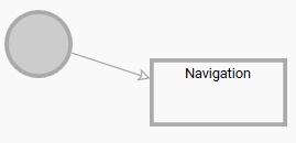
- The Initial State and Navigation State will be connected by the Transition.
With this setting, the transition to the Navigation State has been configured as the initial state of the MainMenu State.
Transition settings between each State
Next, we will set up the transitions between each State (Navigation, Phone, Media).
- From the toolbar at the top right of the State Machine Editor, drag the Transition and drop it onto the Navigation State (the starting side of the transition).
- The Transition (arrow) will appear on the State Machine Editor and be ready to be dragged.
- The Transition (arrow) will appear on the State Machine Editor and be ready to be dragged.
- Extend the Transition (arrow) to the Media State (end of transition) and click.
- The two states, Navigation and Media, will be connected by an arrow.
- The two states, Navigation and Media, will be connected by an arrow.
- With the added Transition selected, click [ Fusion... ] at the bottom left of the State Machine Editor panel.
- The Fusion panel will open, and the Fusion diagram for the Transition will be displayed.
- The Check Click Fusion node is connected to the connector (Condition) at the top right of the Transition Fusion node.
- The Fusion panel will open, and the Fusion diagram for the Transition will be displayed.
- Select the Check Click Fusion node that is connected by default, and press the Delete key.
- The Check Click Fusion node will be deleted.
- The Check Click Fusion node will be deleted.
- Drag the connector (Condition) at the upper right of the Transition Fusion node, move the mouse, and release the left mouse button at the any location.
- The [Select Behavior] dialog will open.
- The [Select Behavior] dialog will open.
- Enter “Check Key Input” in the search field at the top of the dialog.
- The list of behaviors in the dialog will be narrowed down, and Condition > Input > Check Key Input will be displayed.
- The list of behaviors in the dialog will be narrowed down, and Condition > Input > Check Key Input will be displayed.
- Double-click Check Key Input.
- The Check Key Input Fusion node will be linked to the Condition connector of the Transition Fusion node.
- The Check Key Input Fusion node will be linked to the Condition connector of the Transition Fusion node.
- Drag the connector (Actions) at the bottom right of the Transition Fusion node, move the mouse, and release the left mouse button at the any location.
- The [Select Behavior] dialog will open.
- The [Select Behavior] dialog will open.
- Enter “Transition Request” in the search field at the top of the dialog.
- The list of behaviors in the dialog will be narrowed down, and Action > Transition > Transition Request will be displayed.
- The list of behaviors in the dialog will be narrowed down, and Action > Transition > Transition Request will be displayed.
- Double-click Transition Request.
- The Transition Request Fusion node will be linked to the Actions connector of the Transition Fusion node.
- The Transition Request Fusion node will be linked to the Actions connector of the Transition Fusion node.
- Make the following settings for the Transition Request Fusion node.
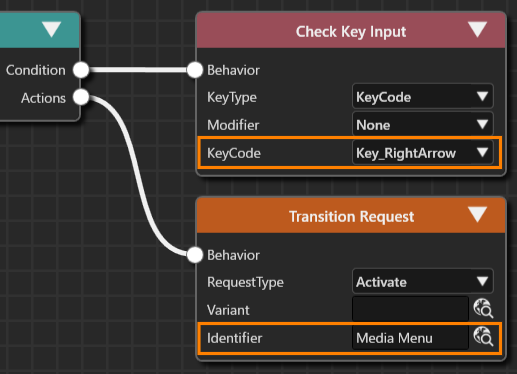
- Clicking the upward-pointing arrow icon in the upper right of the Fusion panel will switch the display to the State.
Check Key Input KeyCode Key_RightArrow Transition Request RequestType Activate Identifier Scenes>Media Menu
- Clicking the upward-pointing arrow icon in the upper right of the Fusion panel will switch the display to the State.
- Repeat the above steps 1 to 11 to set the following five transitions.
- The RequestType for all of these is Activate (default).
Transition
Check Key Input>KeyCode Transition Request>Identifier Media to Phone
Key_RightArrowScenes>Phone Phone to Navigation Scenes>Navigation Navigation to Phone
Key_LeftArrowScenes>Phone
Phone to Media Scenes>Media Menu Media to Navigation Scenes>Navigation
- The RequestType for all of these is Activate (default).
- When all settings are complete, the screen will look like the one below.
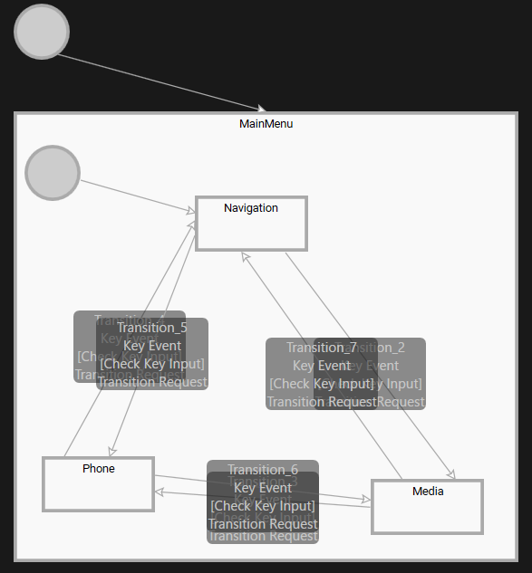
With the above settings, the scene that is displayed when a transition occurs from each scene has been set.
Checking the transition state
Use the Player to check the transition between the states set in the previous section.
Starting the Player
To start the Player, click the [ Play selected scenario ] icon in the toolbar.
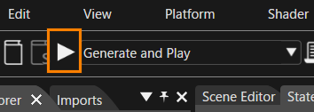
If you have not saved the solution before performing this operation, a dialog box will appear prompting you to save the solution. In this case, click the [ OK ] button in the dialog box. The asset file will be automatically generated and opened in the CGI Player.
Checking the screen transition
Use the Player to check the screen transition.
- Click the [ Play selected scenario ] icon on the toolbar to start the Player.
- Three windows will open, and you can see that the simulation display, one of the windows, displays the “Navi Title” and “Navigation” text, and that the initial transition has occurred to the Main Menu and Navigation scenes.
- Three windows will open, and you can see that the simulation display, one of the windows, displays the “Navi Title” and “Navigation” text, and that the initial transition has occurred to the Main Menu and Navigation scenes.
- By pressing the left and right arrow keys on the keyboard, you can switch the text on the screen and see that you have transitioned to the specified scene.
- Close the CGI Panel and exit the Player.
- All three windows that were open will close.