
State Configuration
CGI Studio enables application logic through an integrated state machine model. State machines, combined with controls and behaviors, support the construction of complex application logic without programming.
This section describes how to set up transitions between scenes using state machines. The ultimate goal is to trigger scene transitions by clicking on specific nodes within a scene.
Opening the State Machine Editor
The state machine editor is displayed by the following operations
- Expand [Solution > State Machines] in the Solution Explorer.
- "State Machines" is expanded and "GlobalStateMachine" is displayed.
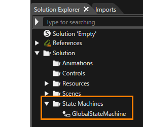
- "State Machines" is expanded and "GlobalStateMachine" is displayed.
- In the Solution Explorer select the "GlobalStateMachine". In the Properties panel check the [IsGlobal] property if it isn't checked already.
- The [IsGlobal] checkbox is checked.
- The "GlobalStateMachine" is global.
- In the Solution Explorer double-click the "GlobalStateMachine".
- The State Machine Editor will be opened.
The State Machine Editor panel can also be opened via the menu bar [View > State Machine > State Machine Editor].
- The State Machine Editor will be opened.
The State Machine Editor displays the GlobalStateMachine's diagram. Like any newly created StateMachine, it contains the following elements:
| Visual representation | Explanation | |
| Initial State | circle | Entry point for the state machine. |
| State |
rectangle |
Represents a certain logic status. OnEntryActions and OnExitActions can be configured. |
| Transition |
arrow |
Transition from one State to another. Sender, Event and Condition for triggering the transition can be configured. |
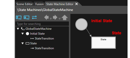
State Configuration for Scene Car_Cluster
The following steps configure the GlobalStateMachine to activate scene Car_Cluster when the entering the State Machine's "State" and to deactivate scene Car_Cluster when exiting the "State".
- In the State Machine Editor select the State.
- The properties of the selected State are displayed in the Properties panel.
- The properties of the selected State are displayed in the Properties panel.
- In the Properties panel, change the [Name] of the General category to "Car_Cluster".
- In the State Machine Editor, the name of the State is changed to "Car_Cluster".
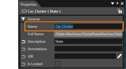
- In the State Machine Editor, the name of the State is changed to "Car_Cluster".
- While "Car_Cluster" is selected in the State Machine Editor, click on the [Fusion...] button in the State Machine Editor's left lower half.
- Fusion will be opened, displaying the Fusion diagram for "Car_Cluster".
- The diagram contains two fusion nodes: Car_Cluster and Transition Request. The Transition Request Fusion node is connected to the Car_Cluster at the On Entry Actions connector.
- In the Transition Request Node, the [RequestType] is set to "Active".
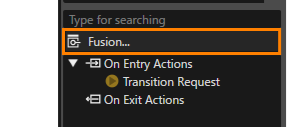
- Fusion will be opened, displaying the Fusion diagram for "Car_Cluster".
- In the Transition Request Fusion node, click on the Select item icon to the right of the [Identifier].
- The [Choose Item] dialog will be opened.
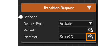
- The [Choose Item] dialog will be opened.
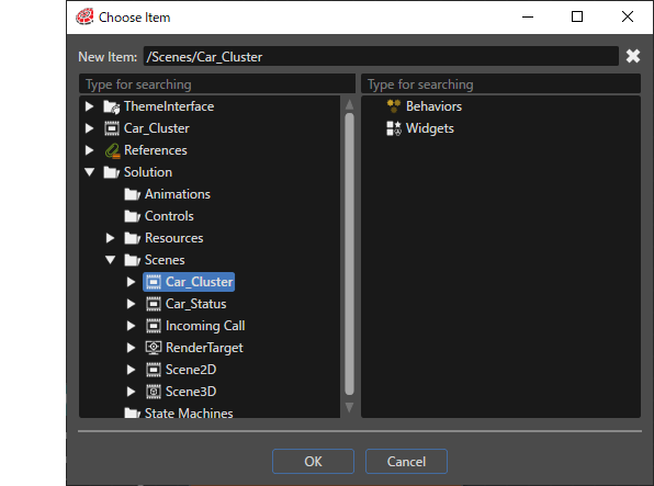
- In the Choose Item dialog, navigate to and select [Solution > Scenes > Car_Cluster], then press the [OK] button.
- The [Choose Item] dialog will be closed.
- With this setting, the "Car_Cluster" scene will be activated when entering State "Car_Cluster".
- In the State Machine Editor, click the Car_Cluster Fusion node's On Exit Actions connector.
- The [Select Behavior] dialog will be opened.
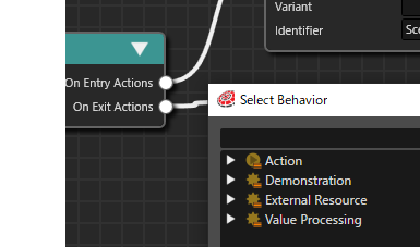
- The [Select Behavior] dialog will be opened.
- In the [Select Behavior] dialog's search field, enter "Transition Request".
- The list of behaviors in the dialog is narrowed down to [Action > Transition > Transition Request].
- The list of behaviors in the dialog is narrowed down to [Action > Transition > Transition Request].
- In the [Select Behavior] dialog, double-click "Transition Request".
- A Transition Request Fusion node is linked to the "On Exit Actions" connector of the Car_Cluster Fusion node.
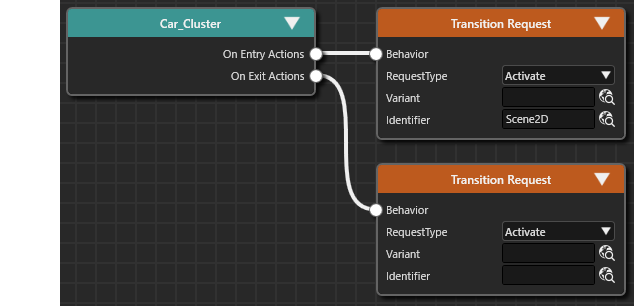
- A Transition Request Fusion node is linked to the "On Exit Actions" connector of the Car_Cluster Fusion node.
- In Fusion configure the newly created Transition Request Fusion node, that is connected to the "On Exit Actions" connector, according to the table below.
- With this setting, the Car_Cluster scene is deactivated when exiting State "Car_Cluster".
RequestType Deactivate Identifier Solution > Scenes > Car_Cluster
- With this setting, the Car_Cluster scene is deactivated when exiting State "Car_Cluster".
- Switch back to the State Machine Editor either via the up arrow icon in the upper right corner of the Fusion panel or using the tabs of the open Scene Composer editors.
- The State Machine Editor is opened, displaying the GlobalStateMachine's diagram
Adding and Configuring States for Scene Car_Status and Incoming_Call
- In the State Machine Editor, select the "Car_Cluster" State. Copy the state either by right-clicking and selecting [Copy] from the context menu or via the keyboard-shortcut <Strg + C>.
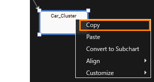
- Click anywhere into the State Machine Editor to deselect the Car_Cluster state. Then paste the state either by right-clicking and selecting [Paste] form the context menu or via the keyboard-shortcut <Strg + P>.
- A State named "Car_Cluster_1" will be added to the State Machine diagram.
- A State named "Car_Cluster_1" will be added to the State Machine diagram.
- In the State Machine Editor, select the new state "Car_Cluster_1". In the Properties panel, change the [Name] of the General category to "Car_Status".
- In the State Machine Editor, the name of State will be changed to "Car_Status".
- In the State Machine Editor, the name of State will be changed to "Car_Status".
- While "Car_Status" is selected in the State Machine Editor, click on the [Fusion...] button in the State Machine Editor's left lower half.
- Fusion will be opened, displaying the Fusion diagram for "Car_Status".
- The diagram contains a Car_Status Fusion node and two Transition Request Fusion nodes, connected via the On Entry Actions and On Exit Actions connectors.
- Fusion will be opened, displaying the Fusion diagram for "Car_Status".
- In Fusion, configure the Transition Request according to the table below.
- The configuration of State Car_Status is completed.
On Entry Actions RequestType Activate Identifier Solution>Scenes>Car_Status On Exit Actions RequestType Deactivate Identifier Solution>Scenes>Car_Status
- The configuration of State Car_Status is completed.
- Repeat steps 1 through 6 above, to add another State for the Incoming_Call scene. Configure the State according to the table below.
- A new state for Incoming_Call has been created and configured.
- In State Machine Editor, the diagram of the GlobalStateMachine looks like in the figure below.
Name Incoming_Call On Entry Actions RequestType Activate Identifier Solution>Scenes>Incoming_Call On Exit Actions RequestType Deactivate Identifier Solution>Scenes>Incoming_Call
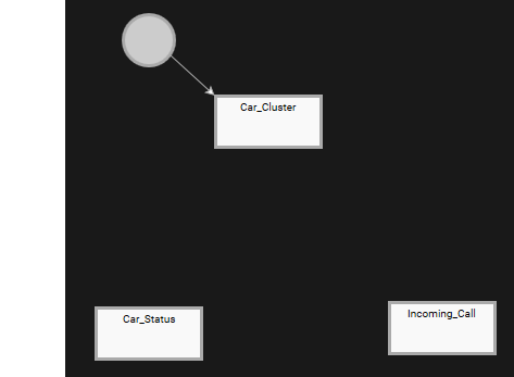
The above operation completes creating States for our Cluster scenes. The next step is to configure the transition logic between these States.