
2D scene composition
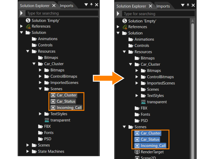
Once the import operation is initiated in the Smart Importer, the data is transformed into editable scenes based on the configurations specified within the Smart Importer. These are located in the Solution Explorer panel under [Resources > Car_Cluster > Scenes].
If the Solution Explorer is not displayed, you can enable it via the menu bar choosing [View] > [Solution Explorer].
Imported Scenes
- In the Solution Explorer move the three scenes to the Scenes folder according to the table below.
- The scenes have been moved as shown in the image below.
Scenes Move From Folder Move To Folder Car_Cluster
Car_Status
Incoming_Call
Solution > Resources > Car_Cluster > Scenes Solution > Scenes
- The scenes have been moved as shown in the image below.
Configure Controls
The default text setting is "Trip: 0000km" for the areas where the Text Value control was applied during import. In order to display the appropriate speed and RPM values, the formatting of the Text Value control must be changed.
- In the Solution Explorer, double-click [ Scenes>Car_Cluster ].
- The "Car_Cluster" scene appears in the scene tree.
- The "Car_Cluster" scene appears in the scene tree.
- In the Scene Tree panel select [SpeedGauge_Group > SpeedValue].
- In the Properties panel the SpeedValue property will be displayed.
- In the Properties panel the SpeedValue property will be displayed.
- In the Properties panel's Control section configure the SpeedValue's properties according to the table below.
- The %d is a format string used in programming, representing a placeholder for text in integer format.
- Represents the way text is dynamically formatted.
Target Item Setting Value Format Text %d Text Alignment center 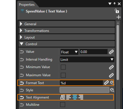
- In the Scene Tree panel select [RPMGauge_Group > RPMValue] and apply the same configuration as for the SpeedValue in step 3.
Control: Behaviors and Fusion
As demonstrated in the previous step, using the Smart Importer for an import operation enables you to apply available controls during the import process. Each item shown in the scene tree is referred to as a node. Nodes with applied controls are marked with the control's distinct icon. A control represents a compound node, consisting of multiple nodes and behaviors designed to achieve a specific functionality.
Behaviors are general-purpose functions that provide interactions or small operations to graphics nodes.
Confirm behavior configuration
The behavior configuration for controls can be viewed following the steps below. The operation is performed on the scene tree of Car_Cluster.
- In the Scene Tree panel double-click the [RPMGauge] control.
- The Scene Tree panel changes from displaying the Car_Cluster scene tree to displaying the Gauge control's tree.
- The behavior configuration of the Gauge control will be displayed in the Extra Scene Tree.
- Additionally, by clicking [ Fusion... ] at the top of the Extra Scene Tree the Fusion panel will be opened, displaying the Gauge Control's Fusion diagram.
- To return to the 'Car_Cluster' view, click the left-arrow button located in the upper-left corner of the scene tree panel.
Fusion combines a behavior tree view, and a properties panel for selected nodes. This provides an alternative way to manage behaviors.
Display Settings
Configure the display in the Render Target panel. This tutorial uses the Empty template, so by default, a camera is configured for a 2D scene (Scene2D\Camera) and a camera for a 3D scene (Scene3D\Camera). Since each scene's camera has been added by importing resources, the next step is to link it to the render target.
For more information on display configuration, see Display Configuration.
- Displays the [Render Targets] panel.
- The [Render Targets] panel is located in the upper right corner of Scene Composer by default.
- If it is hidden, select [Libraries > Render Targets] from the menu bar under "View" .
- Uncheck the default cameras (Scene2D\Camera and Scene3D\Camera).
- The checkboxes associated with the cameras toggle.
Default Cameras Action in Render Targets Panel Scene2D\Camera uncheck Scene3D\Camera uncheck
- The checkboxes associated with the cameras toggle.
- Check the checkboxes for the three cameras added during the resource import (Car_Cluster\DocumentView(0), Car_Status\DocumentView(0), and Incoming_Call\DocumentView(0)).
- The checkboxes associated with the cameras toggle.
Imported Cameras Action in Render Targets Panel Car_Cluster\DocumentView check Car_Status\DocumentView check Incoming_Call\DocumentView check
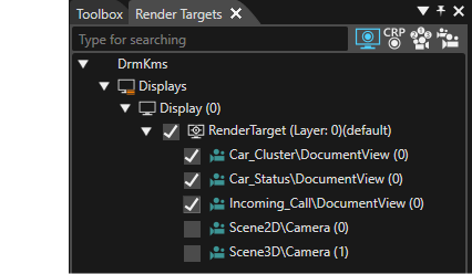
- The checkboxes associated with the cameras toggle.
To see a preview of the display, select [Display > Display-0] from the menu bar under "View".
The 2D scene configuration work is completed. In the next step, we will explain how to configure HMI logic using Fusion.