
3D Editing Helpers
3D Editing Helpers
The SceneComposer offers a set of editing helpers that allow editing 3D scenes as simple and intuitive as possible.
All editing aids, which have a visual presentation, are configurable so that the user can disable them easily if not desired. This can be done from the dialog that opens from "File" - "Preferences" menu under the "Editor" node, the "3D" option.
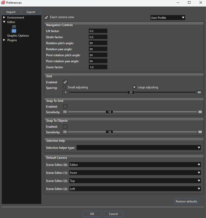
In 3D scenes, SceneComposer offers the following entries in the 3D section of Editor-Preferences:
For more details about Exact camera view, please refer to Other 3D Editing Aids.
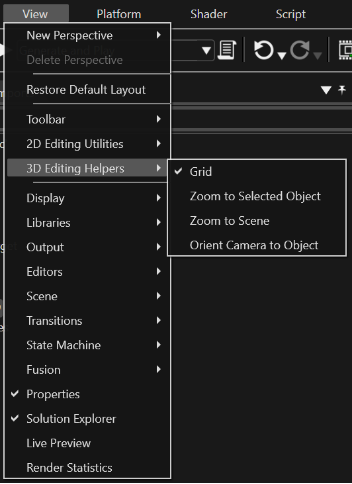
You can also find some 3D Editing Aids in the "View" menu in section "3D Editing Helpers".
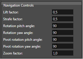
Navigation Controls
Lift factor
Lift refers to up and down moving and the lift factor represents a multiplication factor of moving up and down speed. 0 = no action.
The greater the value the faster the camera is moved. Example values: 1, 1.5, 2
Strafe factor
Strafe refers to sidewise moving and strafe factor represents a multiplication factor of sidewise moving speed. 0 = no action.
The greater the value the faster the camera is moved. Example values: 1, 1.5, 2
Rotation Pitch Angle
Rotation refers to rotation the camera around its position and rotation pitch angle represents the pitch rotation angle applied to the camera after 1 second at full rotation speed (mouse outside of the rotation button).
The angle is specified in Degrees.
Rotation Yaw Angle
Angle represents the Yaw rotation angle applied to the camera after 1 second at full rotation speed (mouse outside of the rotation button).
The angle is specified in Degrees.
Pivot Rotation Pitch Angle
Pivot rotation refers to orbiting - rotation of the camera around a pivot point (a point in the scene) and pivot rotation pitch angle represents the pitch pivot rotation (orbiting) angle applied to the camera after 1 second at full rotation speed (mouse outside of the rotation button).
The angle is specified in Degrees.
Pivot Rotation Yaw Angle
Represents the Yaw pivot rotation (orbiting) angle applied to the camera after 1 second at full rotation speed (mouse outside of the rotation button).
The angle is specified in Degrees.
Zoom Factor
Zoom refers to moving camera forward / backward (perspective) or scaling the camera view (orthographic). The Zoom factor represents a multiplication zooming factor. 0 = no action.
The greater the value the faster the camera is zoomed. Example values: 1, 1.5, 2
Snapping
3D Grid
Enable 3D Grid option, when it is checked, enables the grid in a scene 3D. Grid represents a collection of points (1px) laid at a configurable step size.
- The grid is enabled by checking the checkbox "Enable" from the section Grid, in the "Preferences" - "Editor" - "3D" dialog.
- The grid is rendered in the background.
Snap to Grid
Snap to grid enables an object to become aligned to the grid when being translated.
- When snap to grid is enabled, the grid you set works as a magnet; when a selected object is moved, the grid points appear to pull on it when it approaches. This is useful for accurate placement of image elements.
- Snapping is enabled for all the global bounding box coordinates.
- To enable this feature check the checkbox "Enable" from the section "Snap to grid" and configure the desired sensitivity (the range is the distance to guideline where the object sticks to the point).
Snap to Objects
Snap to objects enables an object to be aligned to another object's rendering area when being translated. The rendering area is the area that bounds the vertices of the bounding box of the object.
- An object will be snapped to the closest other object in its proximity.
- Snapping is available for RenderNodes objects only.
- A render node is in the proximity of another object (thus will be snapped) if one of the eight points of its bounding box is in the proximity of the rendering area of the other object (rendering area is always a not-rotated rectangle and it bounds the points of the bounding box).
- The snap feature can be activated/deactivated by checking/unchecking the checkbox "Enable" from the section "Snap to objects" and the proximity range is configurable using the slide control "Sensitivity".
Positioning
Selection Help
There are three different types available for selection helper.
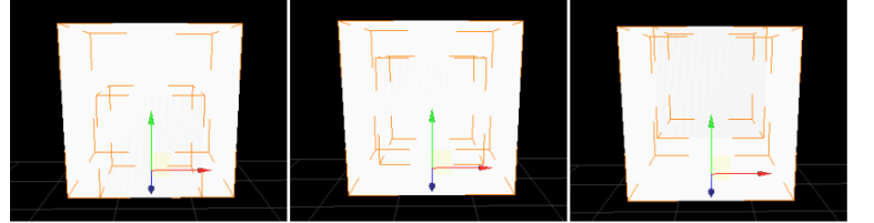
- Bounding box: when this option is selected, the user will be able to see the edges of the surrounding invisible bounding box.
- Region sphere:
- Camera aligned bounding circle: on this mode the camera will always be oriented toward one bounding circle that will surround the bounding box of the selected object.
- Static gimbal: a circle for each axis - X, Y, Z will be displayed - not aligned to the camera.
The bounding circle will be visible just if the "Radius" property under the "Bounding Local Shapes" section will be set at a value greater than 0.
- Both previous types are available. All the modes available for the "Region sphere" type will be available, too.
Object alignment
Object alignment (X Min, X Mid, X Max, Y min, Y Mid, Y Max, Z min, Z Mid, Z Max / relative to other objects): this feature enables automatically re-positioning of selected objects such that they are aligned on a specific criterion.
First selected object serves as reference for alignment.
- It could be very helpful to use any of the predefined orthogonal views (Front, Rear, Top, Bottom, Left, and Right) of the camera.
- The object alignment feature is available for the 3D scenes by selecting the appropriate button from the toolbar. Each button corresponds to a criterion of alignment.
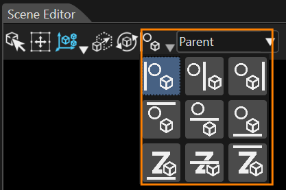
Available criteria
- X Min alignment: the selected objects (excluding the reference one) will be positioned such that the minimum point of the edge which corresponds to the X axis of their global bounding box is aligned to the minimum point of the edge which corresponds to the X axis of the first (reference) object's global bounding box.
- X Mid alignment: the selected objects (excluding the reference one) will be positioned such that the middle point of the edge which corresponds to the X axis of their global bounding box is aligned to the middle point of the edge which corresponds to the X axis of the first (reference) object's global bounding box.
- X Max alignment: the selected objects (excluding the reference one) will be positioned such that the maximum point of the edge which corresponds to the X axis of their global bounding box is aligned to the maximum point of the edge which corresponds to the X axis of the first (reference) object's global bounding box.
- Y Min alignment: the selected objects (excluding the reference one) will be positioned such that the minimum point of the edge which corresponds to the Y axis of their global bounding box is aligned to the minimum point of the edge which corresponds to the Y axis of the first (reference) object's global bounding box.
- Y Mid alignment: the selected objects (excluding the reference one) will be positioned such that the middle point of the edge which corresponds to the Y axis of their global bounding box is aligned to the middle point of the edge which corresponds to the Y axis of the first (reference) object's global bounding box.
- Y Max alignment: the selected objects (excluding the reference one) will be positioned such that the maximum point of the edge which corresponds to the Y axis of their global bounding box is aligned to the maximum point of the edge which corresponds to the Y axis of the first (reference) object's global bounding box.
- Z Min alignment: the selected objects (excluding the reference one) will be positioned such that the minimum point of the edge which corresponds to the Z axis of their global bounding box is aligned to the minimum point of the edge which corresponds to the X axis of the first (reference) object's global bounding box.
- Z Mid alignment: the selected objects (excluding the reference one) will be positioned such that the middle point of the edge which corresponds to the Z axis of their global bounding box is aligned to the middle point of the edge which corresponds to the X axis of the first (reference) object's global bounding box.
- Z Max alignment: the selected objects (excluding the reference one) will be positioned such that the maximum point of the edge which corresponds to the X axis of their global bounding box is aligned to the maximum point of the edge which corresponds to the Z axis of the first (reference) object's rendering area.
Pivot 3D
The translate mode is possible only for the selected object or for the selected objects and its children.
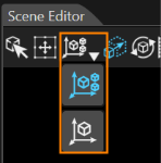
- "ObjectOnly": translate only object
- "ObjectAndChildren": translate object and its children
Default Camera
You can set the default camera for each Scene Editor (Scene Editor -0 through Scene Editor -3). The available default cameras are the Editor Camera, Scene Camera, and Orthogonal Cameras (Front/Rear/Top/Bottom/Left/Right).
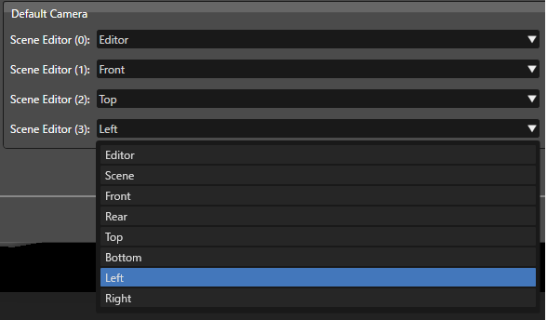
When the default camera is set to "Scene Camera", the first Camera node in the scene, in alphabetical order by name, is used. If the scene does not contain any Camera nodes, the Editor camera will be used instead.
Other 3D Editing Aids
Other 3D editing helpers available in SceneComposer are:
Exact Camera View in Scene Editor
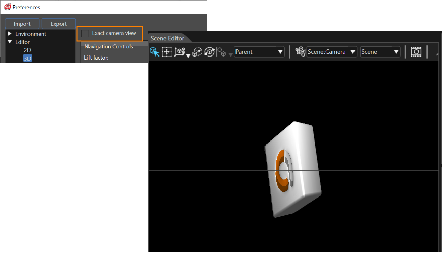
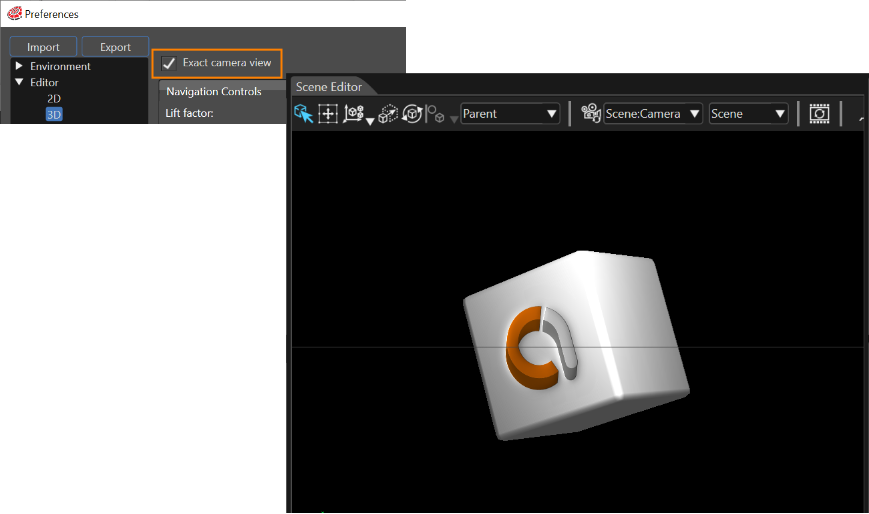
"Exact Camera View" menu option will make the camera from the scene to ignore the current aspect ratio of the scene render.
- When Exact Camera View is disabled the view of the active camera is stretched on the available rendering surface.
- When Exact Camera View is enabled, SceneComposer makes additional computations on the camera so that the camera view image does not get distorted on the scene rendering panel.
- Using this mode may lead to different output compared to the rendering output on display (the display on which the camera renders).
Zoom to Selected Objects
Zoom to selected objects offers a shortcut command by using the "A" key for zoom operation on previous selected object. This functionality is available only in producer camera (perspective and orthogonal camera).
Zoom to Scene
Zoom to scene offers a shortcut command by using the "F" key for zoom operation on the current scene. This functionality is available only in producer camera (perspective and orthogonal camera).
"A" and "F" keys are activating the "Scene" or "Selection" option of the combobox from Toolbar.