
Node Attachments
Node Attachments Toolbox
Create 3D Node Attachments
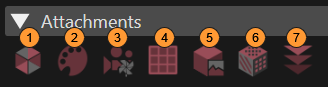
A node can have an appearance attached, having up to four children. Following items from the Toolbox can be used to configure attachments for 3D nodes:
|
1 |
Appearance: Its attributes define the distinctive visualization of a geometry like Mesh, Billboard, and PointSprite. Candera::Appearance |
|
2
|
Material: Describes the color attributes of an object's surface. It is primarily used for lighting computations. Candera::Material |
|
3
|
RenderMode: An appearance component that encapsulates polygon-level and per-fragment compositing render attributes. Read more... Candera::RenderMode |
|
4 |
Uniform Setter: A setter associated to a given node in a 3D scene to generate special effects. Candera::GenericShaderParamSetter |
|
5 |
Texture: A collection of textures. Up to 16 on ES3.0 builds and up to 8 on ES2.0 builds. On ES3.0 builds, additional auto-uniform samplers u_Texture–u_Texture15 and u_CubeMapTexture–u_CubeMapTexture15 are available for binding the 1th–16th textures. |
|
6 |
Cube Map Texture: A particular type of environment mapping. Read more... Candera::GenericShaderParamSetter |
|
7 |
Render Order Bin: Is used to configure a non-default render order for all the 3D objects in a scene graph. Read more... Candera::RenderOrderBin |
Create a new attachment by drag & drop an attachment type from the Toolbox on the desired 3D node in the Scene Tree panel.
Apply Appearance Template to Multiple Nodes
It is possible to apply an attachment to multiple nodes at once: When all the desired nodes are selected, drag and drop the attachment on the multi-selected nodes.
-
If a drag operation is performed between two panels and the destination item is part of a multiple selection, all the items in the selection will be affected.
Render Mode
Configure Render Mode
If no "Render Mode" is associated to an object, SCHost will automatically apply the values set in the Default render mode configuration (the default render mode). Otherwise, if a render mode instance already exists on a specific node, note the following:
In the Properties panel, the RenderMode properties provide a checkbox on the left side with two states:
- "Inherited" (the value is inherited from the default render mode) and
- "Not Inherited" (the value set by the user is the one considered).
If the property value is set to Inherited, the property will be read only and the value will be taken from the DefaultRenderMode (Configuration > Default Render Mode). Only if the checkbox is unchecked (meaning that the property does not inherit from the default render mode configuration) the property will be editable.
-
A new Render Mode added to a node will have all properties set to "Inherited". A RenderMode created based on an imported Scene will have all properties set to "Not Inherited".
Cube Map Texture
Cube Mapping
Cube mapping is one of the most spectacular types of the so called environment mapping. In SceneComposer this type of mapping can be done by using the CubeMapTexture from the Toolbox. First, a mesh and a collection of six images of a cubical environment map have to be imported. The mesh will be dragged in a 3D scene. The Appearance has to be contained:
- Material - does not require any special setting;
- Render Mode - the FrontFaceCulling property has to be selected;
- One of the specific shaders available for the CubeMapTexture (e.g. RefTransCubeMap... shader) - in Appearance the Shader Program that must be selected is RefTransCubeMap_RefCubeMapTex;
- UniformSetter - The uniform setter required by the chosen shader has to be checked
CubeMapTexture supports up to 16 slots on ES3.0 builds and up to 8 on ES2.0 builds (each slot maps to u_CubeMapTextureN).
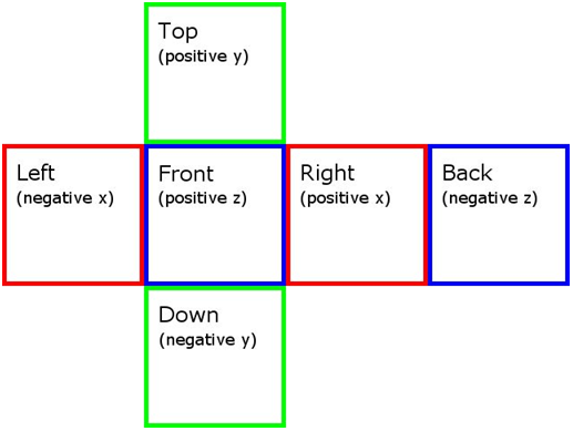
The main feature that has to be used is CubeMapTexture which has to be dragged and set as texture. Six specific properties will become available for this type of texture: Positive X Image / Negative X Image / Positive Y Image / Negative Y Image / Positive Z Image and Negative Z Image. Any of the imported images has to correspond to one of these properties.
-
Any of the imported six images has to be vertically flipped to get the desired map. (This step is mandatory because of the OpenGL standard that stores its textures "reversed".)
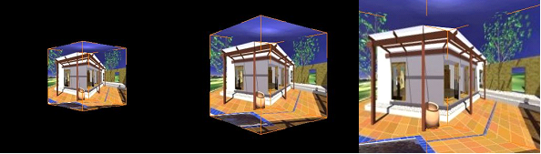
Any model can be placed inside the environment (in our case, a cube) and set as a reflective map. One of the best examples is to place a sphere inside the cube environment and to use the RefTransCubeMapReflection_RefCubeMapTex shader. The setting of the properties will be almost the same as in the Cube mapping case. The UniformSetter properties which have to be enabled are ModelMatrix4, NormalModelMatrix3 and ModelViewProjectionMatrix4. The same six images can be used for the sphere as six textures displayed as an unfolded cube.
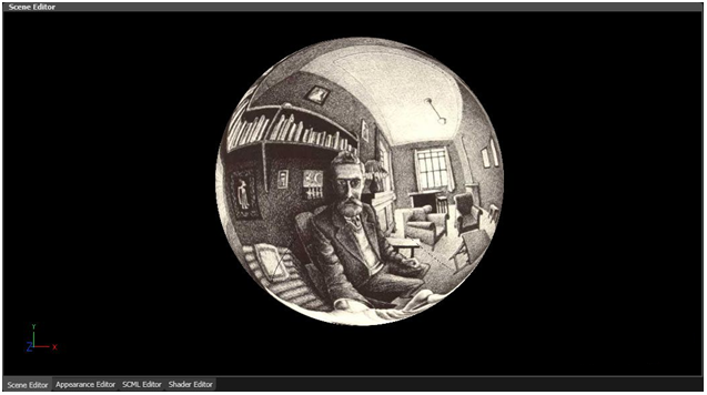
By placing the sphere in an environment some complex and spectacular scenes can be created.
Render Order Bins
Render Order Bins are containers for items to sort them for rendering.
For a detailed description of the Candera Render Order concept, refer to Application and Widget Development Tutorial.
The Render Order Bins collection is displayed in the RenderOrderBins Panel. It can be enabled by choosing "View - Scene - Render Order Bins" menu option.
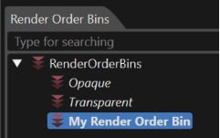
There are two predefined Render Order Bins: Opaque and Transparent. Per default, all objects part of a scene are sorted into that bins according to their render attributes. Both default bins are protected, meaning that they are under control of Candera and cannot be deleted.
Configure a New Render Order Bin
To specify a non-default render order, create a new Render Order Bin by drag & drop from the Toolbox into the RenderOrderBins collection.
- To assign items to the new Render Order Bin, drag items from the scene graph in the "Scene Tree" panel to the Render Order Bin; these items will appear as children of the Render Order Bin.
- Modify Render Order Bin Rank: All the bins are sorted according to the Render Order Bin Rank which is visible as a "read only" field in the Properties panel. If there are many bins dragged from the Toolbox inside the "Render Order Bins" panel, their ranks will be automatically assigned to each of them according with their order. Every time when the user manually rearranges the order of the bins in the "Render Order Bins" panel, their rank is updated.
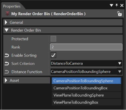
- If property Enable Sorting is checked for the Render order bin, a proper Render Order Rank Criterion must be chosen to define the strategy how the render order shall be calculated.
> If the selected order criterion is "DistanceToCamera" or "ReverseDistanceToCamera", the "Distance Function" will become available. The mentioned function determines how the distance from camera to any node is calculated.
> In case a (Reverse) Render Order Rank Criterion is selected, specify the ranks of the nodes part of a bin on the node property "Render Order Rank". > If the selected order criterion is "BatchOrderCriterion", the "SortbyShaderandRenderMode" and "SortbyAppearance" modes will become available. This criterion produces a render order containing series of nodes that can then be batched by the Renderer to maximize usage of Geometry Instancing.
In order to check the "BatchOrderCriterion" the following steps should be followed:
- Open/create an OpenGL ES 3.0 Solution;
- Import an .fbx object;
- Create a 3D scene containing the object and a camera (do not activate occlusion culling render strategy);
- Create a display, a render target and set the camera to render on the display;
- Clone some meshes and apply a different appearance to them;
- Set up so that shared appearance meshes are not adjacent. Example: CAM < MESH1 MESH2 MESH3 MESH4 MESH5 MESH6 (odd number meshes have shared appearance, others have a different appearance);
- For the Opaque render order bin, enable sorting;
- Sorting by ReverseDistanceToCamera will reduce the number of Instances (0) and increase the Draw Calls (6) (see the "Display Render Statistics" in SceneComposer);
- Sorting by BatchOrder will draw increase the number of Instances (3) and reduce the Draw Calls (4).
-
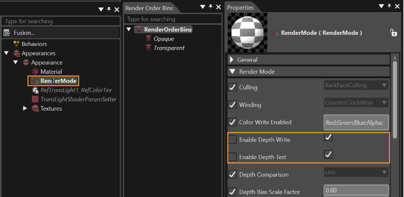
The previous step will lead to the desired results just if a RenderMode object will be associated with every item placed in the Render Order Bin by dragging it from the toolbox panel ("Toolbox" > "Attachments") inside the Appearances section of the Scene Tree. After this operation, the properties "Enable Depth Write" and "Enable Depth Test" which are associated with every RenderMode associated to the items have to be set as in the image below.
- A Render Order Bin can be cloned, deleted or rename like any other scene node. Remove items from a bin with the "Remove From Bin" context menu.
See also:
Node Attachment Templates
SceneComposer allows saving any node attachment (Appearance, Material, Render Mode or Texture) as a template to enable reuse for other nodes. Templates are also listed in the Templates panel.
Save as Template
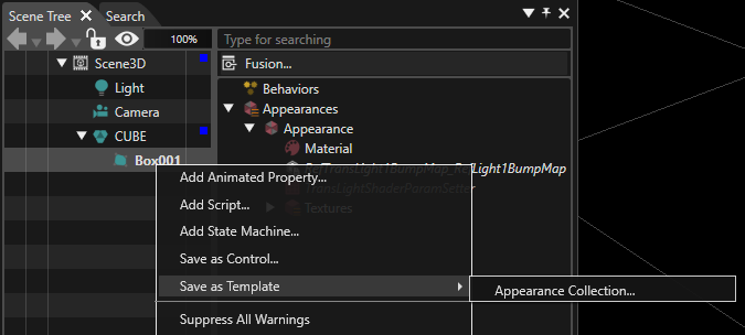
Select a node which contains an appearance, material, render mode, or texture in the Scene Tree and save the selected node attachment as a template with the context menu item "Save as Template".
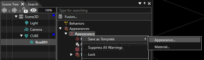
Alternatively directly select the node attachment in the right side of the Scene Tree and use the regarding context menu item to save the selected attachment as template:
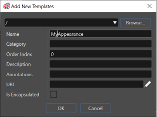
In the "Add New Template" dialog, specify the template location and template name. Tick the checkbox "Is Instance Sharing Enabled" to allow sharing of a template instance across several nodes (refer to the chapter Shared Node Attachments for more details).
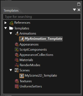
The new template will be displayed in the Templates panel. This panel contains all node attachment templates grouped by type:
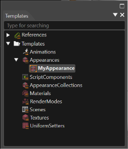
Appearance Wrapper
In some circumstances it could be necessary to expose for the user just those properties which should be modified to get a desired setting of an object. For instance, if the object is a button used in an interface, we can suppose that the only properties which have to be modified by the user are "Font", "Text" and "Status". But if the appearance of the object has many other properties, it could be overwhelming for the user to understand exactly which properties have to be modified to get the desired result. So, it is easy understandable why is necessary to provide a concept which will allow replacing a node attachment with an object which exposes only some properties of a regular node attachment.
This Appearance Wrapper feature allows to expose only some properties of an appearance attached to a node or the properties pertaining to its containments (material, render node, shader, uniform setter, texture). In this way, the goal mentioned above - the user will be able to see and modify just the exposed properties - is fulfilled.
When a template object is created from an existing appearance attached to a node, in the "Add New Template" dialog an Is Encapsulated check-box becomes available. If this check-box is enabled, all the properties associated with the template will not be visible for the user in the properties panel when the template will be used. Only the "Generic" category of properties will be available in the Properties panel.
If the user needs only some of encapsulated properties to be visible, this operation should be done by righting click on the template which has all the properties encapsulated. From the context menu the "Configure Properties" should be chosen. The "Configure Properties" dialog provides the possibility to select which encapsulated properties will become visible in the Properties panel. This operation could be done by using the "IsChecked" boxes available in the dialog. When a template with exposed properties is used, all the properties will become visible in the "Public Properties" category of the Properties panel.
Use a Template
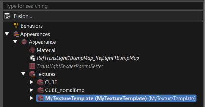
Use a template by dragging it from the Templates panel and dropping it on the desired parent in the Scene Tree:
- An appearance template on a node,
- material, render node and texture on a Appearance.
It's possible to apply the same template to many multi-selected nodes at once. After all the desired nodes are selected, drag and drop the template on the multi-selected nodes.
-
If a drag operation is performed between two panels and the destination item is part of a multiple selection, all the items in the selection will be affected.
The template will replace the existing node attachment by an item linked to the template. In case the template allows instance sharing, the Shared Instance Id used for the node is displayed in brackets.
Edit a Node Attachment Template
Edit a node attachment template in the Properties panel after selecting a template in the Solution Explorer panel or in the Templates panel.
Any change in the template will be reflected in all the nodes using it.
Shared Node Attachments
-
The appearance sharing is only supported for appearance collections.
There are several options:
Prevent sharing of a template:
Disable the property "Is Instance Sharing Enabled" of the node attachment template. In this case, each time such a template is applied to a node, a new instance of the template will be created for this node.
Enable Instance Sharing
Whenever a new node attachment is created and about to be shared, enable the property "Is Instance Sharing Enabled":
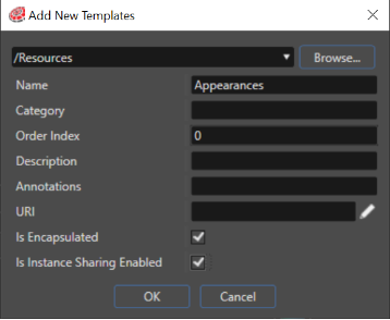
This property can be also set in the Properties panel after selecting an existing template from the Templates panel.
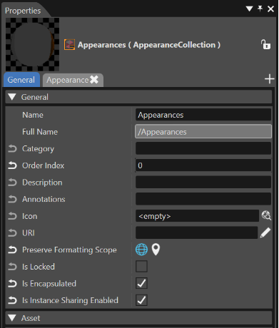
Specify Shared Instance Ids
Node attachments from scenes which are linked to templates having "Is Instance Sharing Enabled" set to true will get a new property "Shared Instance Id" to indicate which shared instance of the node attachment to use:
Edit Shared Instance Ids:
The Instance Id of a node attachment can be edited in the Properties panel of the node attachment.
For an overview of all nodes using a shared node attachment template, use the Instance Id Editor from the context menu of the node attachment template:
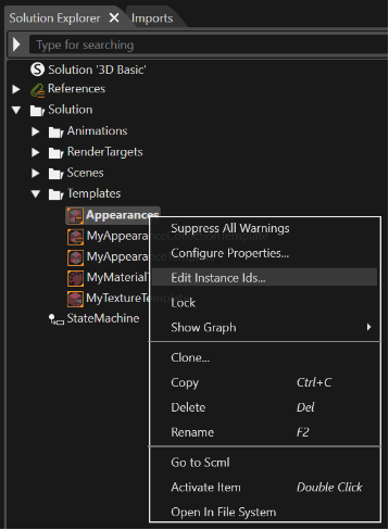
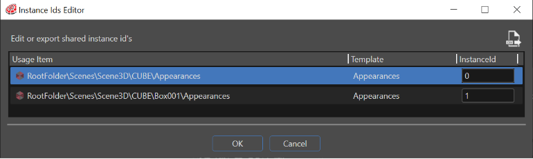
Refer to the Node Attachments Optimization Wizard for optimizing existing scenes regarding node attachments. It is possible to export a .csv file with all the shared items by using the "Export to CSV" button which can be seen in the figure above.
Node Attachment Optimization
SceneComposer provides a wizard to automatically detect node attachments which could be replaced by shared node attachments templates. It is possible to create new node attachment templates, which can be used for the optimization, if no proper node attachment templates exist yet. Selected node attachment candidates can be replaced by shared node attachment templates by the wizard.
Invoke Node Attachment Optimization Wizard
Invoke the node attachment optimization wizard from the context menu of any folder in Solution Explorer panel, or from a scene in the Scene Tree:
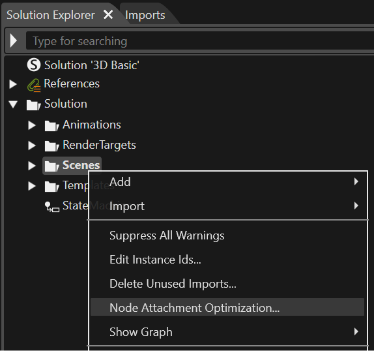
In the Node Attachment Optimization Wizard, select either the entire solution, or a specific scene or location within the solution as root location for the wizard. Further, the type of node attachments to optimize can be selected.
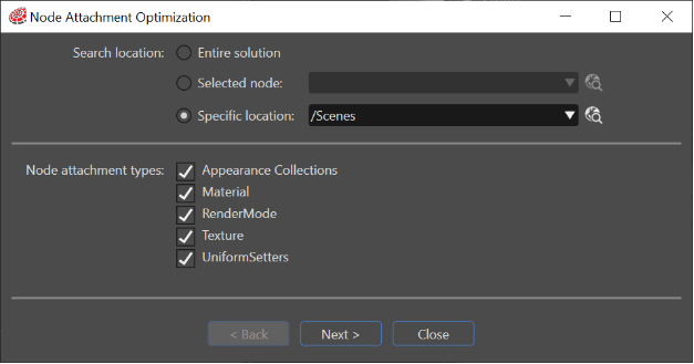
Press the "Next" button to start optimization analysis for the first type of node attachment.
Optimization Analysis Results
During optimization analysis, the wizard detects all nodes with identical properties regarding the selected type of node attachment, and suggests proper node attachment templates to share between those nodes.
As a result of the analysis, the wizard provides a list of node attachment template candidates, which could be shared among several nodes, as well as the number of nodes which would benefit from sharing the same template.
If no proper node attachment template candidate exists yet, the nodes which could share their attachments are listed under the name "( Empty )".
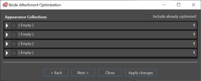
Select "Include already optimized" to include node attachments that have been previously optimized in the list.
Apply Node Attachment Optimizations
Select the node attachment sharing candidates you want to optimize by
- ticking the checkbox in the left side of the result list and
- pressing the arrow button to expand the details for the selected candidate:
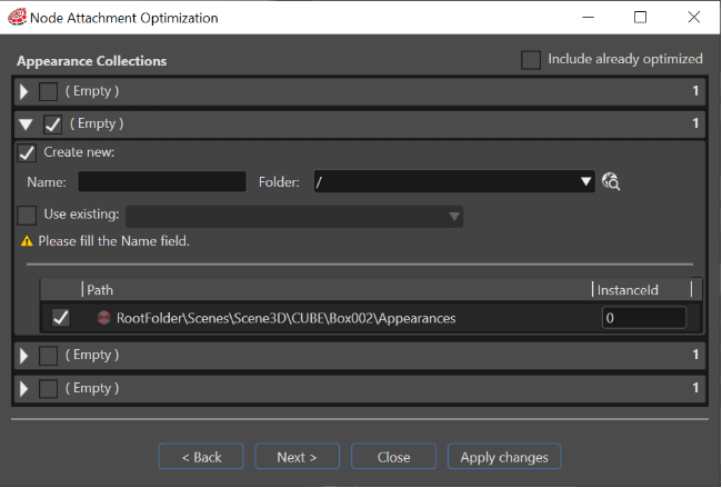
Now all fields to apply the optimization are editable:
- Tick "Create new" if no proper node attachment template exists yet. The wizard will create the proper template in the Templates panel.
- Tick "Use existing" and select the desired node attachment template from the combo box.
In the list below, specify which nodes should share the given node attachment template. The numbers displayed in the right side of each node represents the SharedInstanceId to be used.
Apply the changes by pressing the "Apply changes" button from the upper right corner of the wizard dialog.
Repeat the optimization for all node attachment types which have been selected in the initial wizard step:
- Appearance
- Material
- RenderNode
- Texture
Appearance Editor
The Appearance Editor offers a visual editing and comparison mode for several appearances.
Go to "View" > "Editors" > "Appearance Editor" to activate the Appearance Editor panel. Drag and drop node attachment templates from the Templates panel to the Appearance Editor:
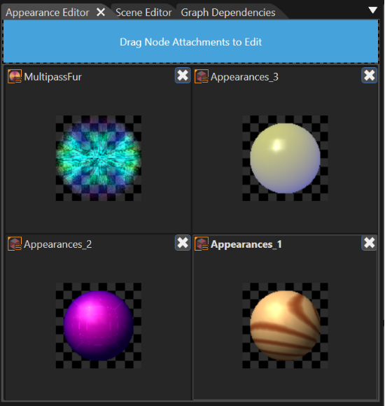
Each of the node attachment template displayed in the Appearance Editor can be selected and then edited using the Properties panel. All changes applied in the Properties panel will be reflected in the Appearance Editor.
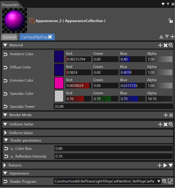
It is possible to apply the same appearance to many multi-selected nodes at once. After all the desired nodes are selected, drag and drop the appearance on the multi-selected nodes.
-
If a drag operation is performed between two panels and the destination item is part of a multiple selection, all the items in the selection will be affected.