
Condition Editor
The Condition Editor is a visual editor for defining conditional expressions as Condition Blockslogic that branchbranches the processing flow based on input devices and the solution state. Conditional logic is managed in Condition Blocks. Within a Condition Block, you createdefine one or more ConditionOutputs that represent the evaluation results (true/false). ConditionOutputs can be reusedreferenced asfrom branchingCondition conditionsnodes in the Action Chain Editor,. andThey bycan assigningalso thembe assigned to the Condition property of behaviors and Fusion, allowing the same conditional logic canto be shared and reused in multiple places across the solution.
Tool UI overview
Panel layout
Double-click any Condition Block in Solution Explorer to open the Condition Editor panel. On this panel, you build a logical expression by placing and connecting Check / AND / OR / NOT nodes. Condition Blocks you create here can be referenced from the Action Chain Editor.
By default, the Condition Editor panel is hidden. To display it, choose View > View Editor > Condition Editor from the menu bar.
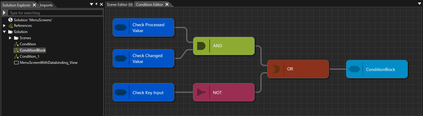
On the Condition diagram diagram,, you can place and connect the following nodes via the context menu. TheWhen you open a ConditionBlockCondition Block in the Condition Editor, a default ConditionOutput node is insertedplaced automatically whenon youthe creatediagram. aConditionOutputs Condition Block and cannotcan be deleted.added or deleted as needed. The properties of any nodenodes placed on the diagram can be edited in the Properties panel panel..
TheA ConditionBlockConditionOutput node represents the overall booleanevaluation result (true/false) of the logical expression defined in the Condition Block.Block. ThisThe valuelogical expression you create in the Condition Editor is usedstored asunder theeach evaluationConditionOutput resultnode whenname theand blockcan isbe referenced from the Action Chain Editor. orThe fromsame ConditionOutput can also be assigned to the Condition property of behaviors and Fusion.Fusion.
| Node type | Description |
|---|---|
| Add Check |
Select a Check node that serves as the entry point for configuring the condition expression. Use this menu to |
| Add AND / OR / NOT | These are logical operator nodes that combine multiple Check nodes and sub-conditions. Use AND / OR / NOT to express composite conditions. |
Basic operations
Create a new Condition Block
Follow these steps to create a new Condition Block:
-
In Solution Explorer, open the context menu at the desired location.
-
Choose Add > New Item.
-
The Add New Item dialog opens.
-
-
In the dialog’s left pane, select Condition Block, then click OK.
-
The value you enter in Name becomes the new Condition Block’s name.
- The Category setting determines which category (location) the Condition Block is registered under in the toolbox.
-
-
A new Condition Block is created in Solution Explorer.
-
At the same time, the Condition Block you created is added to Behaviors in the toolbox.
- For details on where it is placed, see Reusing a Condition Block below.
-
-
Double-click the newly created Condition Block to launch the Condition Editor.
-
On the Condition Editor
panel’spanel diagram,youtherewill seeis a ConditionOutput node named Condition.node whose name matches theCondition Blockname you set in step 3.
-
Reusing a Condition Block
ForThe created ConditionBlock and each ConditionOutput within the ConditionBlock are registered in the toolbox. By dragging and dropping a ConditionBlock or ConditionOutput from the toolbox, you can reuse the same condition logic in the following places:
Also, where a Condition Block appears within the toolbox’s Behaviors categories depends on whether the Category property is set.
If Category is set: A category with the same name is added under the toolbox’s Behaviors, and the Condition Block is shown there.
If Category is not set: The Condition Block is automatically shown under an appropriate category in the toolbox’s Behaviors, depending on the conditions you created,configured.
To check which category it appears in, select the target Condition Block in the Solution Explorer, then see General > Category in the Properties panel.
For the created Condition Block and the ConditionOutput nodes placed within the Condition Block, you can use the standard operations in Solution Explorer to copy,copy, duplicate,duplicate, delete,delete, and rename it.them.
Condition Block category settings
A newly created Condition Block is automatically registered in the Behaviors section of the toolbox. To assign it to a category in the Behaviors section, follow these steps:
In Solution Explorer, select the Condition Block you want to configure.
Its properties appear in the Properties panel.
In the Properties panel, under General > Category, enter a category name.
After entering the category name, press the Enter key. A new behavior group with that name is created in the toolbox’s Behaviors section.
The selected Condition Block is moved into that behavior group.
Creating a Condition diagram
-
In Solution Explorer, double-click any Condition Block.
-
The Condition Editor panel opens.
-
AOn the panel, there is a ConditionOutput node named Conditionnode whose name matches the Condition Block is present on the panel..
-
-
On the right pane, open the context menu, choose Add Check, and select the Condition behavior to use.
-
It is placed on the diagram as a Check node.
-
-
Place AND / OR / NOT nodes as needed and build the logical expression.
-
As needed, add AND / OR / NOT nodes and connect the Check nodes to construct the expression.
-
Connect the
Condition BlockConditionOutput node at the end of the diagram.-
TheLogicalcompletedexpressions created in the ConditiondiagramEditor are saved under the name of each ConditionOutput node and can bereusedreferenced from Condition nodes in the Action ChainEditor.Editor. -
ItThe same ConditionOutput can also beusedassignedasto the Conditioninpropertybehaviorsofandtheincorresponding behaviors/Fusion.for reuse.
-