
Action Chain Editor
Action Chain Editor is a visual editor for composing a View’s event logic on a per-trigger basis. Starting from user input or system events, you can define transitions between Views, play animations, and build complex event-driven behaviors—visually and intuitively—as Action Chain diagrams composed of Trigger, Action, and Condition nodes.
Operations on the Action Chain Editor panel are available only after you have created a View in the View Tree.
In the Action Chain Editor, a Condition node references the Condition Output created in the Condition Editor. You must define a Condition Block—and within it the Condition Output that represents the evaluation result—beforehand.
Action Chain Editor panel UI
Panel layout
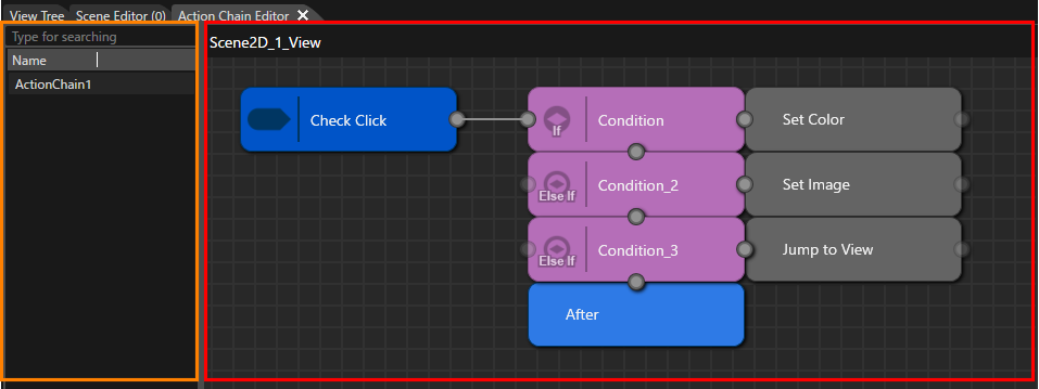
The Action Chain Editor consists primarily of the following two panes.
By default, the Action Chain Editor panel is hidden. To display it, choose View > View Editor > Action Chain Editor from the menu bar.
| UI items | Description |
|---|---|
|
Left pane (orange frame in the figure above) |
Manages multiple Action Chain diagrams in a list. You can organize diagrams by feature or by input device, and perform operations such as creating, opening, renaming, and deleting. |
|
Right pane (red frame in the figure above) |
The workspace for editing the selected Action Chain diagram. Place and connect Trigger, Action, and Condition nodes to define the processing flow. |
Left pane
On the left pane, you can use the context menu to perform the following:
| Menu | Description |
|---|---|
| New Diagram | Create a new Action Chain diagram. |
| Open | Open the diagram selected in the left pane. |
| Rename | Change the name of the diagram selected in the left pane. |
| Delete | Delete the diagram selected in the left pane. |
Right pane
On the right pane of the Action Chain diagram, you can place and connect the following nodes from the context menu. The properties of each node placed on the diagram can be edited in the Properties panel.
| Menu | Description |
|---|---|
| Add Trigger |
Add Trigger Select a trigger node that serves as the entry point of the Action Chain. Use this menu to select the Condition behavior or Behavior Building Block (including Condition behaviors) that you want to use as the trigger. You can also create it by dragging and dropping a Condition behavior from the toolbox. |
| Add Action |
Places a node that represents the action to execute. Select the Action behavior (for example, switching Views or playing an animation) or a Behavior Building Block (including Action behaviors) that you want to use. You can also create it by dragging and dropping an Action behavior from the toolbox. |
| Add Condition |
Select the ConditionOutput created in the Condition Editor, or a Behavior Building Block (including Condition behaviors). Branches the subsequent flow (true/false) based on the evaluation result.
|
| Add After |
Defines processing that must run afterwards regardless of whether the condition evaluated to true or false. Use this to express post-processing or common flows. |
| Add Else | Used together with Add Condition menu to construct an if/else if/else logic structure. |
| Copy | Shown when a node is selected on the right pane. Copies the selected node. |
| Paste |
Shown after performing Copy or Cut. Places a duplicate of the copied/cut node onto the diagram. |
| Cut | Shown when a node is selected on the right pane. Cuts the selected node. |
| Delete | Shown when a node is selected on the right pane. Deletes the selected node. |
Basic operations
Create a new diagram
To create a new Action Chain diagram, first select the target View in the View Tree panel.
-
In View Tree, select the View you want to define an Action Chain for.
-
Open the Action Chain Editor using either of the following:
-
Double-click the target View
-
Right-click the target View and choose Open Action Chain Editor.
-
-
In the left pane of the Action Chain Editor, open the context menu and select New Diagram.
-
A new Action Chain appears in the left pane.
-
Rename the diagram as needed.
-
Place a Trigger node
In an Action Chain diagram, start by placing a Trigger node that specifies “when to run.” The trigger hands off execution to the subsequent Condition group.
Place it on the right pane in either of the following ways:
-
Right-click the right pane and choose Add Trigger, then select the trigger behavior to use from the list.
-
Drag the desired trigger behavior from the toolbox onto the right pane.
Place ConditionOutput and Action nodes
A ConditionOutput (defined within a Condition Block) and an Action together represent one “if line.”
A ConditionOutput node must be created beforehand in the Condition Editor.
-
On the right pane, open the context menu and choose Add Condition to place a ConditionOutput node.
-
This node references a ConditionOutput created in the Condition Editor.
-
- For processing that should run when the ConditionOutput evaluates to true, choose Add Action to place an Action node.
-
Placing an Action node immediately to the right of a ConditionOutput has the following meaning:
Condition_1 + Action_1 → if (Condition_1) { Action_1(); }
-
- Placing another ConditionOutput vertically below an existing ConditionOutput creates an if / else if / else block that is evaluated top to bottom (see the next section, “if/else if/else logic”).
if/else if/else logic
In an Action Chain diagram, you express if / else if / else by how you arrange ConditionOutputs and Actions.
-
Single row (side by side)
-
Placing a ConditionOutput on the left and an Action on the right represents
if (Condition_X) { Action_X(); }(see Case 2 below).
-
-
Stacked conditions in the same column
-
Nested if
Using After nodes
An After node is used to gather the “exits” of multiple branches into one.
-
If you connect lines from multiple Condition rows to the same After node, all of those branches merge at that After.
-
Any Action placed to the right of an After node will always run next, regardless of which path was taken.
-
-
If you insert an After node and then start a new Condition group, you can build a structure that “executes multiple independent
ifblocks in sequence under the same trigger” (see Cases 4 and 5 below). - Even if an After node is present, processing ends there unless you connect an outgoing line. Therefore, placing an After node is not mandatory; however, adding one helps to:
-
Clearly mark the end of a branching block, and
-
Make it easier to add common post-processing later.
-
Action Chain Configuration Examples
This section shows how node arrangements on the Action Chain diagram (right pane) correspond to example if statements.
Case 1: Basic single-condition if
The simplest Action Chain: one condition and one action.
- A trigger (Check Click) detects the event; if the condition evaluates to true, a single action (Set Color) runs.

if (Check Click)
{
    Set Color();
}
Case 2: Nested if (side-by-side layout)
This configuration shows how to represent a nested if that evaluates another condition within the branch of an existing condition.
Arrange the nodes in a single row as: Trigger -> Condition -> Action (Set Color) -> Condition_2 -> Action (Set Color).
- First, if Condition is true, run Set Color.
- Then evaluate Condition_2; if it is true, also run Set Color.
With this horizontal (side-by-side) layout, you can express “an if inside an if” as a nested conditional that is evaluated after the preceding Action.

if (Check Click)
{
    if (Condition)
    {
        Set Color();

        if (Condition_2)
        {
            Set Color();
        }
    }
}
Case 3: Exclusive branching (if / else if)
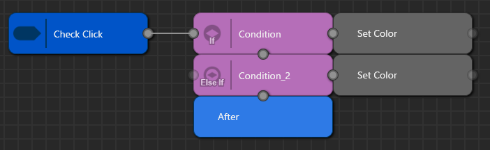
This configuration shows how to evaluate multiple conditions for the same event exclusively (if / else if) so that only one action runs.
Place two rows—Condition and Condition_2—stacked vertically one column to the right of the Trigger, and place their corresponding Actions (Set Color / Set Color) to the right of each row. This represents:
-
Upper row:
if (Condition) { SetColor(); } -
Lower row:
else if (Condition_2) { SetColor(); }
To make the branch’s common exit explicit, place a single After node at the end of the block formed by Condition and Condition_2. The After node denotes “the exit for this if/else if group,” and all subsequent processing should connect to the right of the After node. With this layout, it is visually clear that regardless of which condition is met, the flow ultimately merges into the same continuation.
if (Check Click)
{
    if (Condition)
    {
        Set Color();
    }
    else if (Condition_2)
    {
        Set Color();
    }
}
Case 4: Two independent if blocks under the same Trigger
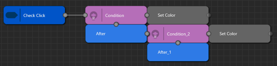
This configuration evaluates two Conditions independently and in sequence within a single Trigger.
- The After placed beneath the
Condition + Set Colorrow is a mandatory exit: the flow passes through it whetherConditionis true or false, and then proceeds toCondition_2.- As a result,
Condition_2is always evaluated, regardless of the outcome ofCondition.
- As a result,
- The After_1 placed beneath the
Condition_2 + Set Colorrow marks the end of the entire chain.
By contrast with Case 3, where stacking ConditionOutputs in the same column and using a single After yields exclusive branching (i.e., the next Condition is checked only if the previous one was false), Case 4 inserts an intermediate After between the rows so that both if blocks are evaluated in order.
if (Check Click)
{
    if (Condition)
    {
        Set Color();
    }
    if (Condition_2)
    {
        Set Color();
    }
}
Case 5: Independent if + subsequent if/else if group
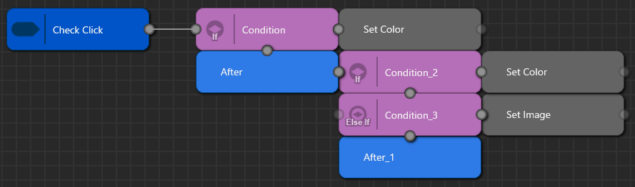
This configuration combines a single standalone if followed by an if / else if branching group under the same Trigger.
-
Row 1 (
Condition + Set Color) corresponds to:if (Condition) { SetColor(); }-
The After directly beneath Row 1 is a mandatory exit. The flow passes through it whether
Conditionis true or false, and then proceeds to the group formed by Condition_2 and Condition_3.
-
-
Rows 2 and 3 (
Condition_2 + Set Color,Condition_3 + Set Image) represent:if (Condition_2) { SetColor(); } else if (Condition_3) { SetImage(); }- When Condition_2 is true, only
SetColor()runs; only when it is false is Condition_3 evaluated.
- When Condition_2 is true, only
-
The After_1 beneath these two rows is the common exit for the
if / else ifgroup.
Compared with Case 4, where both Condition_1 and Condition_2 were independent if blocks, Case 5 has an independent if for Condition_1, followed by an if / else if group formed by Condition_2 and Condition_3.
if (Check Click)
{
    if (Condition)
    {
        Set Color();
    }
    if (Condition_2)
    {
        Set Color();
    }
    else if (Condition_3)
    {
        Set Image();
    }
}
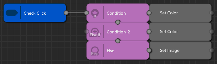
Case 6: Three-way branching (if / else if / else)
This configuration shows a classic exclusive branch with three paths under a single Trigger.
-
Row 1: “Condition + Set Color”
Corresponds toif (Condition) { SetColor(); }.
Set Color runs only when Condition is true. -
Row 2: “Condition_2 + Set Color”
Corresponds toelse if (Condition_2) { SetColor(); }.
Set Color runs only when Condition is false and Condition_2 is true. -
Row 3: “Else + Set Image”
Corresponds toelse { SetImage(); }.
Set Text runs only when both Condition and Condition_2 are false.
The key point is that exactly one Action runs: evaluation proceeds top to bottom and executes the Action on the first row whose condition matches.
if (Check Click)
{
    if (Condition)
    {
        Set Color();
    }
    else if (Condition_2)
    {
        Set Color();
    }
    else
    {
        Set Image();
    }
}
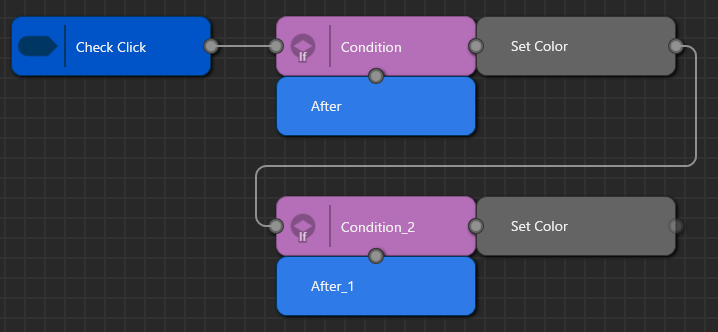
Case 7: Nested if (After-based layout)
This configuration represents a nested if where one ConditionOutput is evaluated only inside the branch of another.
-
The flow goes from the Trigger Check Click to Condition—this is the outer
if (CheckClick). -
The row “Condition + Set Color” corresponds to
if (Condition) { SetColor(); … }. -
Because there is a connector from Set Color down to Condition_2, Condition_2 is evaluated only when
Conditionis true. IfConditionis false, the flow does not proceed toCondition_2. -
The lower row “Condition_2 + Set Color” corresponds to
if (Condition_2) { SetColor(); }. Thus, only when bothConditionandCondition_2are true doSetColor()and thenSetColor()run in sequence. -
After and After_1 serve as visual exits/merge points for the Condition block and the Condition_2 block, respectively.
In contrast to Case 4, where two ConditionOutputs are treated as two independent ifs that are both evaluated, Case 7 places Condition_2 entirely inside Condition, forming a classic nested if structure.
if (Check Click)
{
    if (Condition)
    {
        Set Color();

        if (Condition_2)
        {
            Set Color();
        }
    }
}