
State Machine Panel UI
Opening State Machine Editor
You can open the State Machine Editor using one of the following methods.
Once the State Machine Editor is open, you can switch between it and other editors (e.g. the Scene Editor) by selecting the corresponding tab.
To adjust display preferences for the State Machine Editor panel, open the Preferences dialog via the menu: File > Preferences..., then navigate to Preferences > Environment > State Machine.
State Machine Editor Panel
- Pan the Diagram:
Drag with the middle mouse button to move the State Machine diagram within the editor. - Rearrange Elements:
Use drag and drop to reposition individual elements, such as states and transitions, within the diagram. - Select Multiple Nodes:
Click and drag to draw a selection rectangle around the elements you want to select.
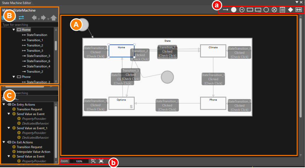
| A | Diagram | Displays the main workspace for the State Machine Editor. |
| B | State/Transition View | Hierarchically displays all States and Transitions defined in the State Machine Editor. |
| C | Behavior/Fusion Configuration | Displays the behaviors configured for the currently selected element (e.g., State or Transition) in the diagram. By clicking the Fusion button, the Fusion Editor panel will appear, showing Fusion-specific configurations. |
| a | Top Toolbar | Contains icons representing elements for constructing a state machine. These can be dragged onto the diagram to create and configure your state machine. |
| b | Bottom Toolbar | Provides tools for zooming and panning the diagram's display. |
State/Transition View
This view displays all elements of the State Machine (states and transitions) in a hierarchical tree format. When you select an element in the tree, the corresponding element is also automatically highlighted in the diagram on the right. This synchronized selection allows you to edit and check each element intuitively and efficiently.
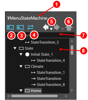
| 1 | State Machine Name |
Displays the name of the State Machine currently selected in the Solution Explorer. If a Subchart is open, its fill path is shown. |
| 2 |
show current subcharts only |
Switches the content displayed in the editor tree.
|
| 3 |
show subchart details |
Switches the Subchart content displayed in the editor tree.
|
| 4 |
show transitions |
Toggles the visibility of Transitions in the editor tree.
|
| 5 | Navigation Buttons |
Works similarly to a web browser's "Back" and "Forward" controls. They allow you to browse through the display history of state machines in the diagram, making it easy to revisit previously viewed diagrams. |
| 6 | Hierarchy Navigation Button | Enables you to switch from a detailed Subchart view back to a higher-level hierarchy view. This feature helps you easily transition between Subchart-specific details and the overall state machine structure, ensuring better navigation and context awareness. |
| 7 | Search Field | Allows you to quickly locate States or Transitions within the editor tree by entering keywords. When a match is found, the corresponding element is automatically highlighted in both the editor tree and the diagram. Additionally, its details are displayed in the properties panel for easy review and editing. |
| 8 | Editor Tree | Displays all elements configured in the diagram, such as States, Transitions, and other components, in a hierarchical tree structure. |
Behavior/Fusion Configuration
This panel displays the behaviors associated with the currently selected State Machine element (State, Transition, etc.). To configure or edit complex behavior logic, click the Fusion... button to open the Fusion Editor.
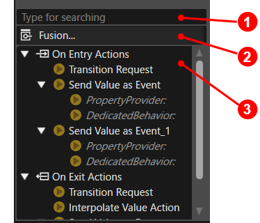
| 1 | Search Field |
Allows you to quickly locate behaviors in the Behavior View by entering a string of characters. If a behavior that includes the keyword you entered is found, it is automatically highlighted and its details are displayed in the Properties panel, enabling easily review and editing. |
| 2 | Fusion button |
Opens the Fusion Editor and displays the Fusion diagram for the selected element (such as State, Transition, etc.). This allows you to configure and edit Fusion-specific configurations. |
| 3 | Behavior View |
Lists all behaviors configured within the currently selected element (State, Transition, etc.). |
Top Toolbar
The toolbar at the top of the diagram provides icons for the elements that make up a State Machine. To add elements such as States, Transitions and other components:
- Drag the desired icons from the toolbar.
- Drop it into the State Machine diagram.
This intuitive drag-and-drop functionality makes it easy to build and customize complex State Machines
For detailed information about each component, please refer to Components in State Machine.

| 1 | Transition | A Transition defines the movement between States based on specified conditions and actions. |
| 2 | Initial State |
The Initial State represents the starting point of the State Machine's execution. |
| 3 | History State | The History State stores the last State within a Subchart and resumes execution from that state when the Subchart is re-entered. |
| 4 | State |
A State represents a specific point in the State Machine. Specific actions and conditions can be processed at both when entering and exiting the state. |
| 5 | Subchart | A Subchart is a structural element that groups States and Transitions into a single unit, simplifying the management of complex State Machines. |
| 6 | Entry Point | An Entry Point is a pseudo-state that enables controlled entry into a Subchart. |
| 7 | Exit Point |
An Exit Point is a pseudo-state that enables controlled exit from a Subchart. |
| 8 | Note | A Note is a visual element used to organize and display supplementary information and design details related to State Machines. |
| 9 | Choice | A Choice is used to branch transitions based on conditions. |
| 10 | ViewState | A ViewState controls the visibility of a specific View within the State Machine. |
Bottom Toolbar
The toolbar at the bottom of the diagram provides controls for display magnification and other functions related to the diagram's visualization. These tools help you adjust the view for easier navigation and editing of complex State Machine diagrams.
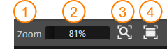
| 1 | Zoom | Click on the "Zoom" text to reset the State Machine diagram to a 100% zoom factor. |
| 2 | Zoom Slider | Use this zoom slider to adjusts the display magnification of the diagram. |
| 3 | View whole layout |
This function automatically scales the view so that all elements in the diagram fit within the display area. |
| 4 | Switch to selected node | Centers the view on the currently selected element in the diagram. |