
Basic Operation
CGI Studio 3.13 and later supports "Undo and Redo" operations in State Machine Editor. (However, adding/deleting/editing Inflection Point of a transition is not supported.)"Undo and Redo" operations, see Undo and Redo Operations for details.
State Machine asin the menuMenu itemBar
FromThe the [ State Machine ] menu in the menu bar, offers the following options can be selected.options.
| New State |
Select this option |
| Connect to the currently running CGI Panel. After selecting this option, the |
|
| Validate Active State Machine | Select this option to perform validation on the currently active State Machine. |
How to createCreate a newNew State Machine
There are two ways to create a new State MachineMachine:
1. Create fromState Machine in Solution Explorer
AfterInselectingthe Solution Explorer, right click anylocationfolderon(e.g.theSolution).SolutionExplorer- The
suchcontextasmenuSolutionwillfolder,open.
[Add New Item]dialogboxappears.
2. Create fromState Machine via the menu barMenu
- From the menu bar, select
[State Machine > New State Machine...].- The
[Add New State Machine]dialogboxappears.
- The
- Configure the available settings (e.g. location, name) in the dialog and
pressclicktheOK.[OK - A
]newbutton at the bottom of the dialog.
Multiple State MachinesMachine canitem will be created in the selected location within the Solution Explorer.
Multiple State Machines can be created using the Multiple Clones approach in the Solution Explorer.
Each State Machine is associated with a specific scope defined by its placement. For example, you can create a different State Machine for each scene to manage behavior according to scope.
Adding a State Machine to anya node in the scene treeNode (State Machine behavior)
When a State Machine is created for a node in the scene tree, it is automatically associated with that node. Once the association is complete, the State Machine can be configured using the State Machine Editor.
AfterInselectingthe Scene Tree panel, right click any nodeinof the scenetree,tree.- The context menu will open.
- The
[Add New State Machine]dialogboxappears.
TheA new State Machine item will be created in the selected location within the Solution Explorer.
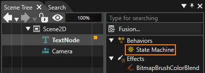
The addedA State Machine created like this is automatically connected as a State Machine behavior in the extra scene tree of the target node. This connection allows the State Machine to receive all events generated by the target node and trigger the appropriate action based on the predefined logic. This mechanism allows for more intuitive and efficient control by linking visual elements (nodes) with behavioral logic (State Machines).
GlobalStateMachine Settings

Enabling the [ Is Global ] property in the StateMachine Properties
section sets the
Each State Machine can operate either as a GlobalStateMachine.Itglobal appliesor toa alllocal scenesState inMachine. When you create a new, empty Scene Composer solution, a global State Machine is included by default. Any newly created State Machine is a local State Machine unless you explicitly enable the solutionIsGlobal andproperty starts(see workingfigure automaticallybelow).
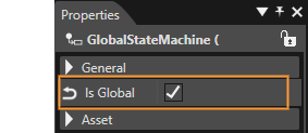
Multiple GlobalStateMachines can be set up as needed. This featurecapability canallows be leveragedyou to manage complexcomplex, solution-wide behavior by coordinating logic that applies across theall entire solution.scenes.
Global State Machine
TheA Global State Machine is a State Machine that affectsapplies to the entire solution.solution. It is appliedactive toacross all scenes contained in the solution, and startsbegins operating automatically when the solution starts.
- If an event
thatoccursaton any node in the Scene Tree and is not handled by a Local StateMachine,Machine, the event is forwarded to the Global StateMachineMachine,receiveswhichandcanhandlesthenit.process it according to its defined logic. ItYouiscanpossibleconfigureto setmultiple Global StateMachines.Machines.AllEachGlobalofState Machinesthem can receive and handle events that were nothandledprocessed by any Local StateMachinesMachines, enabling flexible, solution-wide control andhandlescoordinationit.of behavior.
Local State Machine
A Local State Machine is a State Machine that is explicitly associated with a specific node (an element within anthe application).
- Local State Machines receive all events
fromgenerated by the node they are connectednode.to. ItYouiscanpossibleconfigureto setmultiple Local StateMachines.Machines for the same node. If an event is not handled byaany of these Local StateMachine,Machines, it is passed on to other Local State Machines and ultimately to any Global State Machineswill receive the event..
A newly created State Machine is a Local State Machine by default.default. To changeconvert thisit tointo a Global State Machine,Machine, checkenable the [ Is Global ] boxoption as described above.
Priority of Transitions
When multiple transitionsTransitions areoriginate connected tofrom the same State, thetheir priority of the transitions can be setconfigured in the following two ways. BasedThe onState thisMachine priority,evaluates conditionTransition matchesconditions are checked in order of priority,priority, withand the first Transition that satisfies thewhose condition firstevaluates beingto true is executed.
This featuremechanism is especiallyparticularly useful when multiple transitionsTransitions haveshare the same occurrencetriggering condition,condition, allowingas forit clearallows controlyou ofto expectedclearly define which Transition should take precedence and ensures predictable, well-controlled behavior.
Settings on the State/Transition view
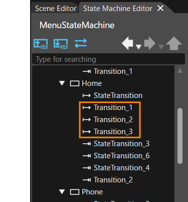
Transitions are displayed in a treeviewtree view in the upper upper-left corner of the State machineMachine editor.Editor. In this tree view, Transitions are listedordered from top to bottom inaccording orderto oftheir priority.priority - the Transition at the top has the highest priority, and the one at the bottom has the lowest.
TheYou can easily change the priority can be easily changed by dragging and dropping withTransitions within the mouse.tree view. For example, in the caseconfiguration shownhighlighted in orange in the orange framefigure below, Transition_1 has the highest priority and Transition_2Transition_3 has the lowest priority.

Settings on the Properties panel
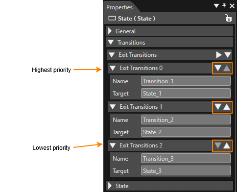
Transitions pointing away from a certain State are called exit transitions. All exit transitions that have already been set for thea targetcertain State are displayed in the [properties panel in the Transitions > Exit Transitions ]section. sectionIn ofthis list, Transitions are displayed from the targettop State'sto Properties panel. They are listed herebottom in order of priority, fromwith topthe tohighest-priority bottom.Transition at the top.
The priority orderYou can be easily changedadjust the priority using the [Move Item Up and Move Item Down ] and [ Move Item Up ] icons (orange boxedorange-highlighted area in the figure below)figure). For example, in the figure below, Exit_Transitions 0 (= Transition) has the highest priority and Exit_Transitions 2 (= Transition_2) has the lowest priority.

Add an Element
Each element placedavailable in the State Machine Editor uppertop toolbar can be draggedadded and dropped ontoto the diagram.diagram Pleaseusing notedrag-and-drop. When placing elements, observe the following restrictions when placing the elements.restrictions:
OneOnly one Initial State can be placedonin each State Machine.- History
State/States, EntryPoint/Points, and ExitPointPoints canonlybe placedinonly inside aSubchart.Subchart.
These constraints ensure correct State Machine structure and prevent invalid configurations.
Add a Transition
The procedure for interconnectingInterconnecting States usingwith Transitions is a two-step process described below.process:
- Drag and Drop a Transition
Drag a Transition from the top toolbar and dropa TransitionFrom the upper toolbarit onto the source State,to be connected with the Transition dragged. At this point, movereleasing the mouseto visually confirm that the arrow is being dragged.button. - Select the destination State
Move the mouse towards the destination State. As you do so, a Transition arrow will stretch from the source State to the mouse cursor. Drag the arrow onto to the destination State andclickcomplete the connection with a mousetoclick.
This procedure establishes a Transition linking the selected source State to the chosen destination State.
Transition Inflection Points
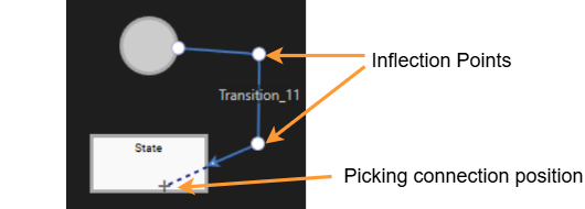
You can add a Inflection Point to the location you click by holding down the Ctrl key while clicking on a Transition that has already been placed on the diagram. By adding an inflection point, you can change the display form of the transition on the diagram.

Changing Element Size
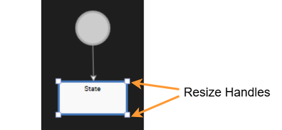
State/History State/Subchart/Note can be resized to any size on the diagram. After adding it on the diagram, you can resize it by dragging the resize handle with the mouse.

Deleting an element
Elements placed on the diagram of the State Machine Editor can be deleted by doing the following
- After selecting the element to be deleted on the diagram, press the Delete key.
-
In the editor tree on the State/Transition view, select the element to be deleted, then press Delete (or select [ Delete ] from the context menu).
Subchart
In addition to dragging and dropping a Subchart from the top toolbar onto a diagram, you can also place it on a diagram by converting it from an existing State.
Converting to Subchart
A State can be converted to a subchart by selecting "Convert to Subchart" from the context menu after selecting the State to be converted. The original State name is still used after conversion, but can be changed to any name if necessary.
Entry Point/Exit Point's Placement and Display
Entry/Exit Points can be placed along the edges of the Subchart. This clearly defines the flow in and out of the Subchart. When viewing the Subchart on a diagram, these points are also visually indicated, making it easier to grasp the overall flow. Entry/Exit Points can be freely rearranged. Appropriate placement of Entry/Exit points further optimizes the structure of the State Machine and makes the design easier to understand.
Note
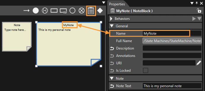
You can add Note to your diagrams in the State Machine Editor. To add a Note, drag the Note from the State Machine Editor toolbar onto the diagram.
Note can be resized in the same way as States, using the resize handles. Note titles can be edited in the Properties panel. Clicking on a Note puts it in text editing mode.

Design Options
When State/Transition is selected on a diagram in the State Machine Editor, the following context menu appears.

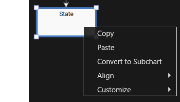
| Copy | Copies each selected element. The copied elements can be pasted onto the diagram using the Paste operation. |
| Paste | Pastes a copied element onto a diagram. However, this does not work for some elements such as Transitions. |
| Convert to Subchart | Convert the selected State to Subchart. See here for details. |
| Align |
When multiple items are selected while holding down the Ctrl key, the display position of the selected items can be aligned. The alignment can be selected from Left, Center (left/right), Right, Top, Center (up/down), Bottom, Distribute Horizontal, and Distribute Vertical. |
| Customize |
Decorate the State with any image or fill it with any color. For details, please refer to Changing Styles. |
Changing Styles

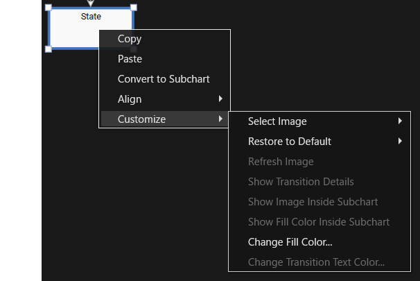
The following are the selections available for Customize menu.
Select Image
Set the background image for State. There are two ways to set it.
| From Solution Explorer... | The [ Select Item ] dialog opens, allowing you to select any image. It is assumed that the images that can be selected have been imported into the solution beforehand. |
| From Local File... | Opens the Windows OS Select File dialog where you can select any image. |
Restore to Defaults
Restores the default settings for elements for which design options are enabled. The range of default settings can be selected from the following menu.
| All | Resets all design settings for the target element to default. |
| Image | Only the image set for the target element will be restored to default. |
| Fill Color | Only the fill color set for the target element will be restored to default. |
| Transition Text Color |
Only the Transition text color will be restored to default. |
| Transition Details Visibility | Only the Transition detail display settings will be restored to default. |
| Connection Type |
Only the Transition connection type (line type) will be restored to default.(The default settings for Transition connection types can be found in Preferences). |
Refresh Image
This option is only available if an image is already selected for the target State. Reload the image from a file or create a new screenshot from the scene/camera.
Show Transition Details
When this option is enabled, the detailed information portion of the text content displayed in the Transition, such as actions, will be hidden.


Show Image Inside Subchart
This option is only available for State in Subchart. If this option is enabled, the image set for the State can be displayed as the Subchart background image.

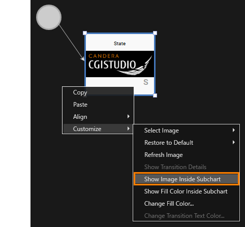
Show Fill Color Inside Subchart
If the "Change Fill Color" option (described below) is set for the target State, enabling this option will cause the background color set for the State to be reflected in the Subchart background color.
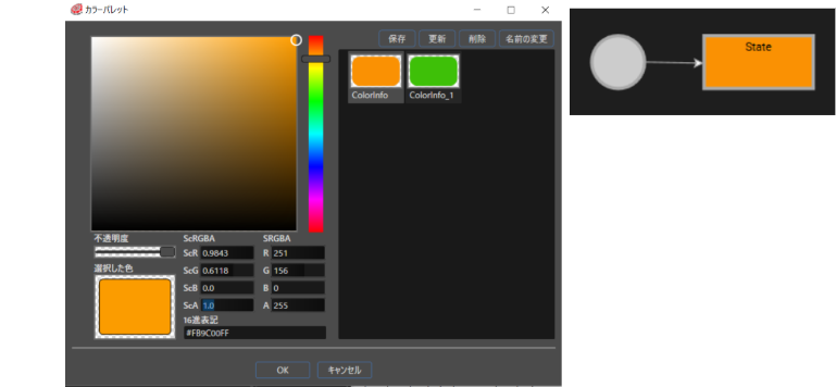
Change Fill Color
You can change the background color of the State. Selecting this option opens the [ Color Palette ] dialog, set the desired color and click [ OK ].

Change Transition Text Color
You can change the name text color setting for Transition. Selecting this option opens the [ Color Palette ] dialog, set the desired color and click [ OK ].
Using Shortcut Keys
In the State Machine Editor, you can use shortcut keys to perform some operations more efficiently. This allows you to perform tasks such as adding items easily and quickly.
Operation Procedure with Shortcut Keys
-
Mouse over
Move the mouse cursor to any location or element on the diagram. -
Check for shortcut keys
All available shortcut keys are displayed in the lower left corner of the Scene Composer. -
Enter a shortcut key
Select one of the displayed shortcut keys you wish to use and enter it on the keyboard.- In the example below, Transition, State, Subchart, Choice, Initial State, History State, and Note can be added with shortcut keys. You can add notes by using the shortcut keys.

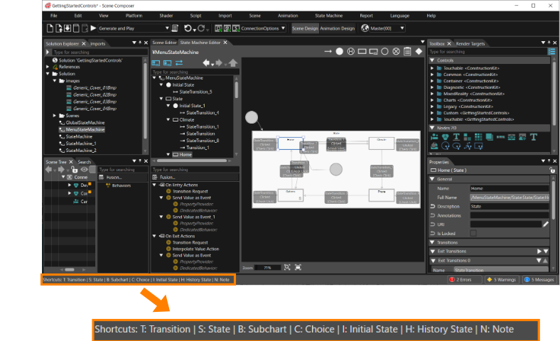
Diagram Bird's Eye Function
The Diagram Bird's Eye panel can be displayed by selecting [ View > State Machine > Diagram Bird's Eye ] from the menu bar. This panel provides a bird's eye view of the entire State Machine Editor panel. For more information on how to view the panel and basic operations, see Diagram Bird's Eye.
Starting with CGI Studio 3.13 , the State Machine Editor supports "Undo and Redo" operations, enabling safer and more flexible editing of State Machine diagrams.
Limitation: Adding, deleting or editing of a Transition's Inflection Point is not supported by the Undo/Redo feature.
For more information, see Undo and Redo Operations.