
Target setup for NXP RT117X
Required Tools and Equipment
The following tools and equipment are needed to set up and run the project:
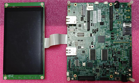
- NXP RT117X hardware board with display
- CGI Studio (Minimum version 3.15.1)
- CMake GUI
- Visual Studio Code
- Ninja Build Tool
- Required binary files (.bin)
- IAR Embedded Workbench
- Board Support Packages
- Hardware Variants
Hardware Revision Supported Display Supported BSP versions Notes Rev_a 720 × 1280 only Up to BSP 2.16 BSP versions higher than 2.16 are not supported Rev_b 720 × 1280 or 800 × 480 (Raspberry Pi Display) 2.16 and newer
(e.g., 25_06_00)Supports newer BSP versions
Hardware Connection Setup
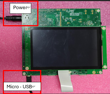
- Connect the power cable to the NXP RT117X board.
- Connect the Micro-USB port on the board to a USB-A port on your laptop or PC.
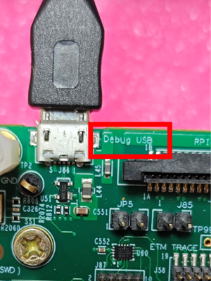
- Make sure the Micro-USB is connected to the USB Debug port.
- Power on the board.
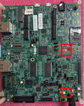
- Check if the power LEDs on the board are glowing.
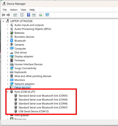
- Wait for your system to detect the board. You can verify this by checking Device Manager → Ports (COM & LPT) — a new COM port should appear for the NXP RT117X board.
Scene Composer Configuration
- Open Scene Composer and create a new solution using the Empty Sample Solution template.
- Select and import multiple images into Scene Composer from the following path:
(CGI-ROOT/cgi_studio_content/2D/Paid_Stock_Images) - Drag and drop the imported images into the Scene Editor.
- In the Scene Editor, adjust the images by scaling and rotating them as needed.
- Add the following elements to the Scene Editor:
- One Solid Color Node
- One Text Node
- One Button
- Open the Render Target tab (next to the toolbox) and select an available render target.
- In the Properties panel, set the following values:
- Orientation:
- 90 ° for 720x1280/Portrait mode displays.
- 0° for 800 x 480/ Landscape mode displays.
- Width: 720
- Height: 1280
- Orientation:
- Click on Display (0) under the Render Target tab.
- In the Display properties, set the X and Y resolution to match the Render Target resolution.
- Navigate to File → Solution Options → General Configuration.
- Finally, generate the Target Asset.
VS Code Configuration
- Open Visual Studio Code (VS Code) from the CGI root directory.
- Navigate to the toolchain file as per the hardware revision (rev_a/rev_b) and BSP version used, refer the following table to select the necessary toolchain file:
Toolchain Table:
For Eg: If using a Rev_b hardware version with BSP version 2.16, navigate to the following file.Hardware Revision Toolchain file Description Rev_a IAR-toolchain-RT117X_Native2D.txt Rev_a without Touch IAR-toolchain-RT117X_Native2D_Touch.txt Rev_a with touch enabled display Rev_b IAR-toolchain-RT117X_Native2D_B.txt Rev_b without Touch support IAR-toolchain-RT117X_Native2D_B_Touch.txt Rev_b with Touch enabled display IAR-toolchain-RT117X_Native2D_B_Touch_2.16.txt Rev_b with Touch enabled display
and BSP version 2.16
(CGI-ROOT/cgi_studio_devices/src/RT117X/ToolchainFiles/IAR-toolchain-RT117X_Native2D_B_Touch_2.16.txt) - Open the file and make the following edits:
- Disable touch (only if the display does not support touch)
set (CGIDEVICE_TOUCH_ENABLED OFF CACHE BOOL "Enable Touch support"). - Update the BSP path to match the local directory.
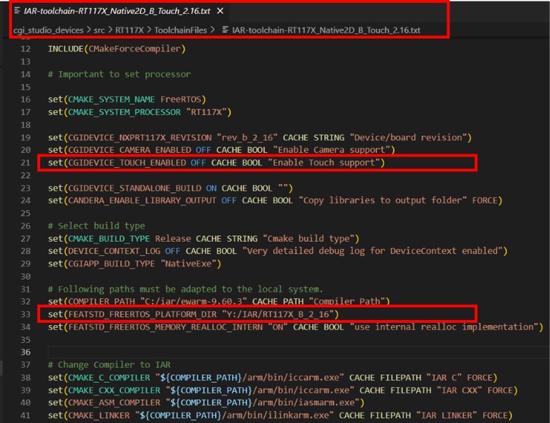
- Disable touch (only if the display does not support touch)
- Next, open the following file and update the display configurations as required:
(CGI-ROOT/cgi_studio_devices/src/RT117X/CourierPlatformDefs/Target_FreeRTOS_RT117X
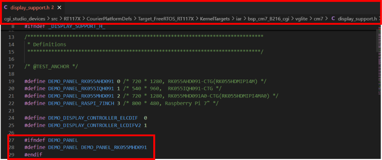
/KernelTargets/iar/bsp_cm7_B216_cgi/vglite/cm7/display_support.h) - In this file, go to line 28 and update the display panel configuration as shown below:
- Before:
#define DEMO_PANEL DEMO_PANEL_RASPI_7INCH //DEMO_PANEL_RK055MHD091 - After:
#define DEMO_PANEL DEMO_PANEL_RK055MHD091
This removes the commented-out section and sets the display to RK055MHD091.
- Before:
Project Configuration using Cmake GUI
- Open CMake GUI.
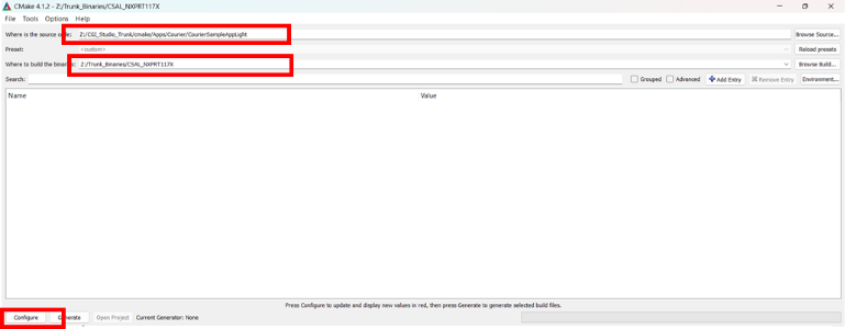
- Set the source code folder to:
(CGI-ROOT\cmake\Apps\Courier\CourierSampleAppLight) - Set the build folder (the location where build files will be generated).
- Click Configure.
- When prompted, select Ninja as the generator.
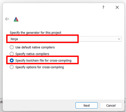
- Specify the toolchain file for cross-compiling refer the toolchain table, select the appropriate toolchain file as per the hardware version:
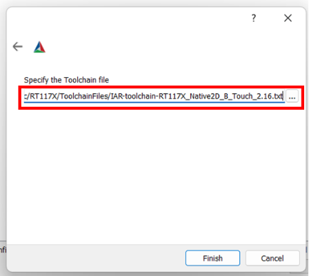
- Click Finish → Next.
- Click Configure again until all red entries disappear, then click Generate.
- Close CMake GUI.
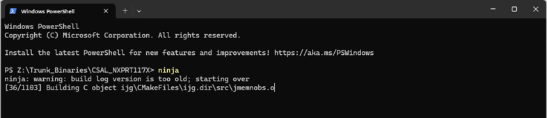
- Open terminal in the build folder and give a ninja build.
- Run the following command
ninja
Adding Assets
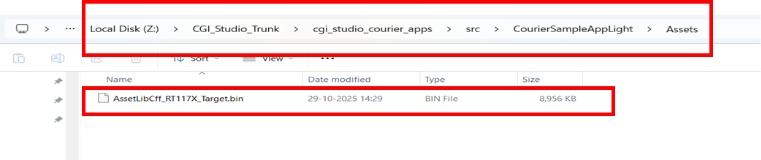
- Create an Assets folder in:
CGI-ROOT\cgi_studio_courier_apps\src\CourierSampleAppLight - Add the generated asset file to this folder.
- Rename it to:
AssetLibCff_RT117X_Target.bin
Flashing and Execution
- Open the generated project from the following path:
BUILD-ROOT\iar_project\debug_cm7_B_cgi\CGI_RT117X.ew
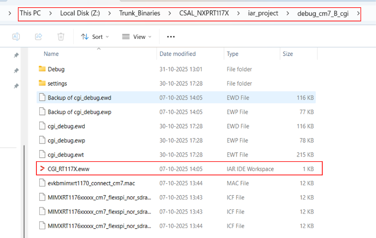
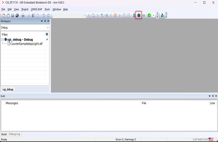
- IAR Embedded Workbench IDE will launch automatically.
- Click Download and Debug to flash the binary to the hardware.
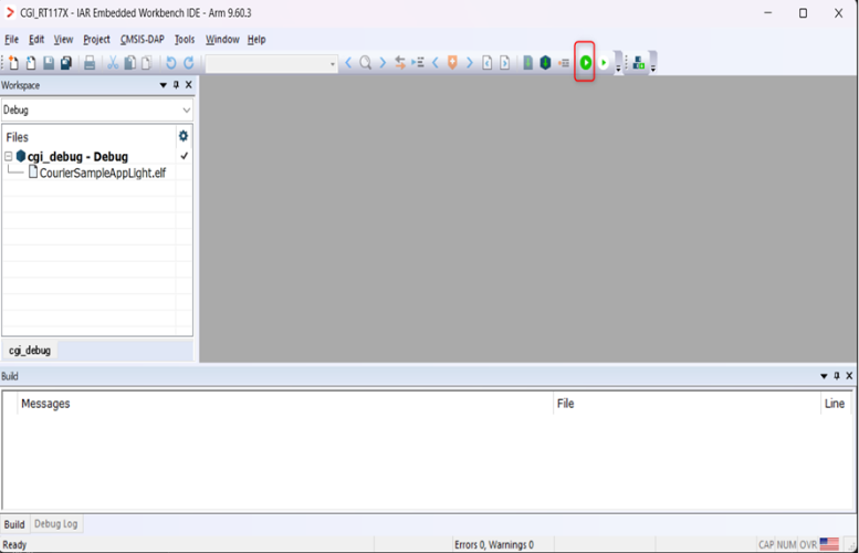
- After flashing, click GO in IAR to start execution.
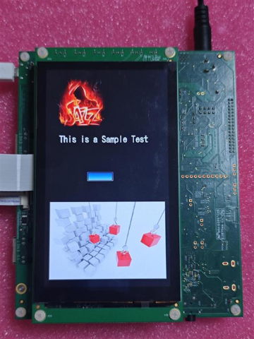
- Observe the output on the display connected to the NXP RT117X board.
Verification
- Confirm that the display output matches the expected layout from Scene Composer.
- Check that images, colors, and animations render correctly.
- Validate Bitmap Stride behavior for both aligned and unaligned images.
- Ensure there are no visual distortions or flickering.
Blend mode mapping
Following are the mapping from OpenGLES blend mode to NXP-RT supported blend modes.
VG Image blend mode mapping (VGLite API 3.x, available only in BSP version 25.06):
1)OPENVG_BLEND_SRC : sF=One, dF=Zero, sAF=One, dAF=Zero
2)OPENVG_BLEND_SRC_OVER : sF=SourceAlpha, dF=InverseSourceAlpha, sAF=One, dAF=InverseSourceAlpha
3)OPENVG_BLEND_DST_OVER : sF=InverseDestAlpha, dF=One, sAF=InverseDestAlpha, dAF=One
4)OPENVG_BLEND_SRC_IN : sF=DestAlpha, dF=Zero, sAF=DestAlpha, dAF=Zero
5)OPENVG_BLEND_DST_IN : sF=Zero, dF=SourceAlpha, sAF=Zero, dAF=SourceAlpha
6)OPENVG_BLEND_MULTIPLY : sF=DestColor, dF=Zero, sAF=DestAlpha, dAF=Zero
7)OPENVG_BLEND_SCREEN : sF=One, dF=InverseSourceColor, sAF=One, dAF=InverseSourceColor
8)OPENVG_BLEND_ADDITIVE : sF=One, dF=One, sAF=One, dAF=One
VG Image blend mode mapping (VGLite API 2.x, available only in BSP version 2.16):
1)VG_LITE_BLEND_NONE : sAF=One, dAF=Zero
2)VG_LITE_BLEND_DST_IN : sAF=Zero, dAF=SourceAlpha
3)VG_LITE_BLEND_SRC_OVER : sAF=One, dAF=InverseSourceAlpha
4)VG_LITE_BLEND_SRC_IN : sAF=DestAlpha, dAF=Zero
5)VG_LITE_BLEND_DST_OVER : sAF=InverseDestAlpha, dAF=One
6)VG_LITE_BLEND_MULTIPLY : sF=DestColor, dF=Zero, sAF=One, dAF=InverseSourceAlpha
7)VG_LITE_BLEND_SUBTRACT : sF=InverseSourceColor, dF=One, sAF=One, dAF=One
8)VG_LITE_BLEND_SCREEN : sF=One, dF=InverseSourceColor, sAF=One, dAF=InverseSourceColor
9)VG_LITE_BLEND_ADDITIVE : sF=One, dF=One, sAF=One, dAF=One
PXP Image blend mode mapping:
1)kPXP_PorterDuffSrc : sAF=One, dAF=Zero
2)kPXP_PorterDuffAtop : sAF=DestAlpha, dAF=InverseSourceAlpha
3)kPXP_PorterDuffOver : sAF=One, dAF=InverseSourceAlpha \n
4)kPXP_PorterDuffIn : sAF=DestAlpha, dAF=Zero \n
5)kPXP_PorterDuffOut : sAF=InverseDestAlpha, dAF=Zero \n
6)kPXP_PorterDuffDst : sAF=Zero, dAF=One \n
7)kPXP_PorterDuffDstAtop : sAF=InverseDestAlpha, dAF=SourceAlpha \n
8)kPXP_PorterDuffDstOver : sAF=InverseDestAlpha, dAF=One \n
9)kPXP_PorterDuffDstIn : sAF=Zero, dAF=SourceAlpha \n
10)kPXP_PorterDuffDstOut : sAF=Zero, dAF=InverseSourceAlpha \n
11)kPXP_PorterDuffXor : sAF=InverseDestAlpha, dAF=InverseSourceAlpha \n
12)kPXP_PorterDuffClear : sAF=Zero, dAF=Zero \n
13)kPXP_PorterDuffMax : sAF=One, dAF=One \n\