
Components in State Machine
The State Machine is created by combining components such as “State” and “Transition”. These elements are used to construct rules that define a series of states, a series of possible inputs, and another state or transition to itself in response to the input.
The following eight types of elements can be used as components of a State Machine in the Scene Composer. These can be selected from the toolbar at the top of the State Machine Editor panel and placed on the diagram.
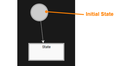
Initial State
The Initial State is a special state that indicates the starting point of the state machine. There is always one of these in each state machine, and when the state machine is executed, processing always starts from this Initial State.

State
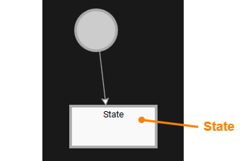
A State represents a specific logical state. It indicates the current operation and conditions within a State Machine, and specific actions can be performed when a State starts or ends. All actions associated with a State are executed sequentially when a State starts (OnEntry) or ends (OnExit). These actions can be set in the properties panel or Fusion editor after selecting the target State.

Transition
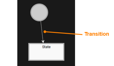
A Transition represents a connection between two States and are executed when specific conditions are met. Transitions aggregate the sending object, condition, and action. If the condition evaluates to true, the action is executed. Transitions are evaluated based on the logical order defined.
In addition, if multiple transitions are connected to the same state, you can set the priority of the transitions. For details, see here.

Subchart
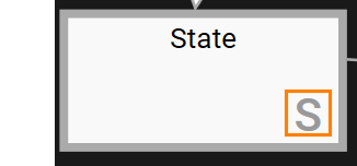
A Subchart is a structure that groups one or more States and Transitions. The lower right corner of a Subchart in the diagram is marked with an “S” to distinguish it from a normal State.

Subcharts can be connected to other States and Subcharts on the diagram, allowing you to create flexible flow structures. Double-clicking on a Subchart will display the details within it. As they can be edited independently of the main diagram, they can be used to organize complex logic in an easy-to-understand way.


Entry/Exit Point
A Entry Point and a Exit Point are pseudo-states that enable controlled entry and exit to and from a Subchart. They function as clear starting and ending points for entering a Subchart. By setting multiple Entry Points, you can start a Subchart from different points depending on the conditions. Similarly, by setting multiple Exit Points, you can provide different exits depending on the conditions.

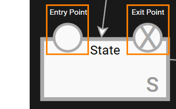
Example of Subchart Configuration Using Entry/Exit Point
The following is a simple example of a configuration using a Subchart and Entry/Exit Points.

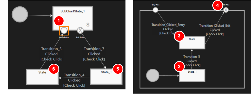
In the figure above, the Subchart "SubChartState_1" is placed on the diagram.
- The state machine starts the transition from the Initial State on the diagram, and then moves to Subchart "SubChartState_1" and transitions to the Initial State in the Subchart (see diagram 1 above).
- A mouse click causes a transition to State_1 of the Subchart (2 in the above figure). Subsequently, mouse click operation causes a sequential transition to State and Exit Point of Subchart (3 and 4 in the above figure).
- As a result, the state machine transitions from Subchart to State_1 of the diagram (5 in the previous figure).
- Subsequent mouse clicks will transition to the diagram State (previous figure 6).
- A mouse click on this State triggers Transition_3, which is connected to the State, and thus re-enters the Subchart via the Entry Point (orange frame area in the above left diagram) again and returns to the State in the Subchart (above diagram 2).
History State
A History State is a special State that is placed within a Subchart, and it has the role of remembering the state in which the Subchart was last active. This makes it possible to resume processing from the State immediately before exiting when transitioning back to the Subchart. Subcharts that contain a History State are marked with an “H” in the top right corner.

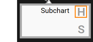
Example of History State Configuration
The following is a simple example of a configuration with a History State placed in the Subchart.

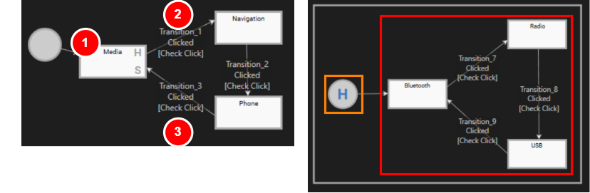
In the figure above, the Subchart "Media" with History State is placed on the diagram.
- The state machine starts its transition from the Initial State on the diagram, and then moves to Subchart "Media" (see diagram 1 above).
- It first passes through the History State (orange boxed area in the above figure) and enters the State loop (red boxed area in the above figure) starting with State "Bluetooth".
- The state machine will remain in this Subchart as long as transitions between Bluetooth, Radio, and USB are triggered.
- When Transition_1 on the diagram (2 in the diagram above) is triggered, this Subchart will exit.
- When the Subchart ends, History State remembers the State in the Subchart immediately before the exit.
- If the state machine transitions again to Subchart "Media" via Transition_3 (Figure 3 above), it transitions to Subchart "Media" again.
- History State remembers the State of the last transitioned Subchart "Media".
- Therefore, the transition is restarted from the last transitioned State in the Subchart "Media".
When entering the Media state as well as when exiting the Media state, OnEnter of the Media state as well as OnEnter of the stored most recently selected Media device state (Bluetooth/USB/Radio) will be called.
See State Machine Solution for a sample state machine solution using History State.
Note
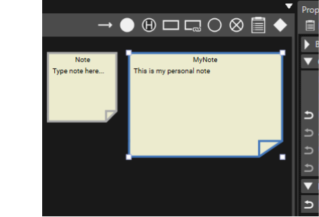
In a State Machine Editor, you can add Note to the diagram to supplement the information. This helps you to visually organize the design content and notes.

Choice
Choice allows you to branch Transitions. This makes it easy to edit state machines that define different behaviors based on multiple conditions.
Example of Choice Usage
In the State Machine diagram below, the transition starts from the Initial State on the diagram and transitions to the Evaluate State.

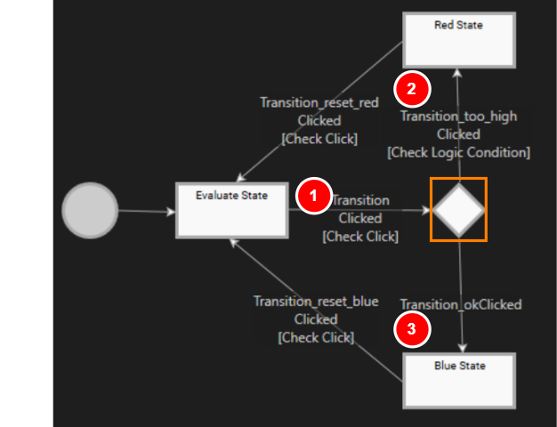
- When the button is clicked in the Evaluate State, Transition (1 in the above figure) is executed, and the transition moves to Choice (orange frame section in the above figure), where the Transition branches.
- In the Transition "Transition_too_high" (2 in the above figure), the processed value is checked to see if it exceeds a specific threshold value.
- If the condition is met: Transition to "Red State" if the value is too large (2 in the above figure).
- If the condition is not met: If the value is below the threshold, Transition_okClicked is executed and a transition to the "Blue State" is made (3 in the above figure).
The priority of a Transition (Exit Transition) connected to a Choice is the same as the normal Transition priority change procedure.
By utilizing Choice, multiple conditions can be clearly organized within the state machine, making it easier to visually grasp the branching structure. This makes it possible to design complex logic in a simple manner.
ViewState
ViewState is a dedicated State for controlling whether a specific View is shown or hidden within the state machine. It works with the View defined in the View Definition Editor and switches screens in sync with state transitions via the ActivateView action set in On Entry/On Exit Actions.
You can create a ViewState either from the State Machine Editor toolbar or by dragging and dropping a View from Solution Explorer onto the State Machine Editor diagram.
Create from a View
To create a new ViewState from a View in Solution Explorer:
In Solution Explorer, select any View.
Drag the selected View and drop it onto a blank area of the State Machine Editor diagram.
A new ViewState is placed on the diagram.
Assign an ActivateView action to both On Entry Actions and On Exit Actions of the created ViewState.
Configure the properties of the ActivateView action set on On Entry/On Exit Actions as described below.
Activate View On Entry Actions True Specify the view that was dropped. On Exit Actions False Specify the view that was dropped. These settings establish the basic flow in which this View is displayed while this State is active.
Place into an existing State/Subchart
To place a View inside an existing State or Subchart:
In Solution Explorer, select the target View.
Drag the View from Solution Explorer onto the State Machine Editor diagram and drop it on the State or Subchart you want to use as the transition source.
A new ViewState is placed inside the target State/Subchart.
A Transition from the containing State/Subchart to this ViewState is created automatically.
Its Condition is automatically set to Jump to View.
Assign an ActivateView action to both On Entry Actions and On Exit Actions of the ViewState.
Configure the properties of the ActivateView action set on On Entry/On Exit Actions as described below.
Activate View On Entry Actions True Specify the view that was dropped. On Exit Actions False Specify the view that was dropped. These settings let you configure a flow in which, when processing completes, the state machine transitions to the state that displays this View.