
Components in State Machine
TheA State Machine diagram is createdbuilt by combining core components such as “State”States and “Transition”.Transitions. TheseTypically, elementsa set of states are usedinterconnected through transitions to constructrepresent rulesthe that define a seriesflow of states, a series of possible inputs, and another state or transition to itself in response to the input. logic.
The following eight types of elements can be used as components of a State Machine in the Scene Composer. These cancomponents beare selectedavailable fromin the toolbar at the top of the State Machine Editor panel and placedcan onbe added to the diagram.
action.
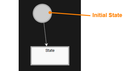
Initial State
The Initial State is a special state that indicatesmarks the starting point of the stateState machine.Machine. ThereEvery isState alwaysMachine contains exactly one ofInitial theseState. in each state machine, and whenWhen the stateState machineMachine is executed, processing always startsbegins from this Initial State.
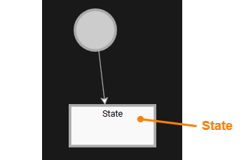
State
A State represents a specific logical state.condition within a State Machine. It indicatesreflects the current operation and conditionscontext withinof athe Statesystem. Machine, and specificSpecific actions can be performedexecuted when a State startsis entered or ends.exited:
These actions can be setconfigured in the propertiesProperties panelPanel or the Fusion editorEditor after selecting the target State.
Transition
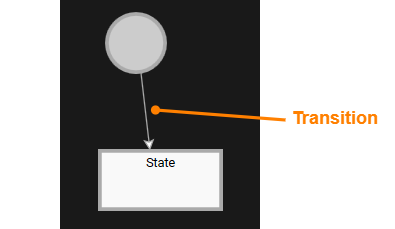
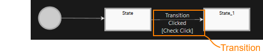
A Transition represents a connection between two States and areis executed when specific conditions are met.Each Transitionstransition aggregateconsists of:
Transitions are evaluated based onin the logical order defined.
Inwithin addition,the ifState Machine. If multiple transitions areoriginate connected tofrom the same state,State, you canan setassign thepriorities priorityto ofdetermine thewhich transitions.transition should be executed first. For more details, see here.
Subchart
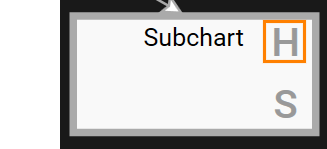
A Subchart is a structure that groups one or more States and Transitions.Transitions Theinto lowera single unit. In the diagram, the lower-right corner of a Subchart in the diagram is marked with an “S”S” to distinguish it from a normal State.
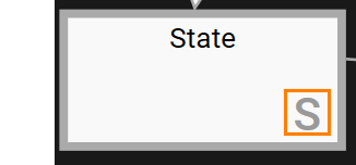
Subcharts can be connected to other States andor SubchartsSubcharts, onenabling the diagram,creation of flexible and modular flow structures. Double-clicking a Subchart opens its internal details, allowing you to createview flexibleand flowedit structures.its Double-clickingcontents.
Because a Subchart will display the details within it. As theySubcharts can be edited independently of the main diagram, they canare beideal usedfor to organizeorganizing complex logic ininto ansmaller, easy-to-understand way.sections.

Entry/Exit Point
A Entry PointPoints and a Exit PointPoints are pseudo-states that enable controlled entry into and exit to and from a Subchart.Subchart. They functionserve as clear starting and ending pointspositions for enteringnavigating a Subchart.
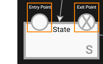
Using Entry and Exit Points enables the creation of modular and condition-driven flows within complex State Machine diagrams.
Example of Subchart Configuration Using Entry/Exit Point
The following isexample shows a simple exampleconfiguration ofthat incorporates a configuration using a Subchart along with Entry Points and Entry/Exit Points.Points.
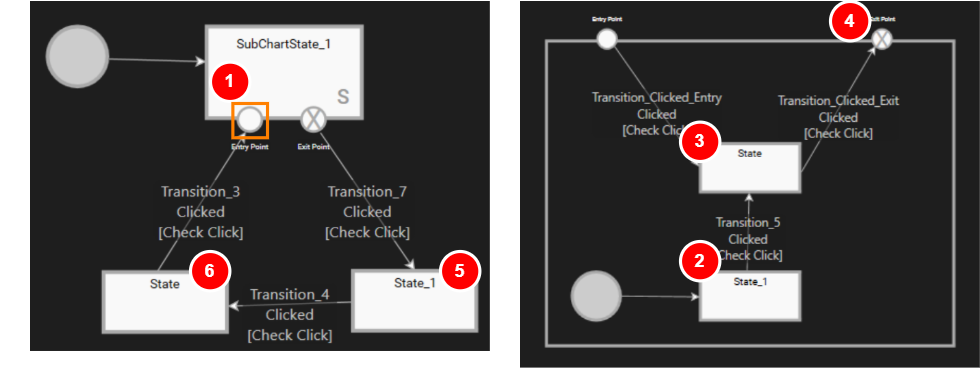
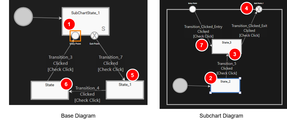
In the figure above, the Subchart named "SubChartState_1" is placed onwithin the State Machine diagram.
- The state machine starts
the transition fromat the Initial Stateonin thediagram,baseanddiagramthen(seemoveslefttofigure above). From there it transitions into the Subchart state "SubChartState_1".
- The state machine starts
History State
A History State is a special State that iscan be placed withininside a Subchart,Subchart. andIts itpurpose hasis to remember the rolelast ofactive rememberingstate within the Subchart. When the flow transitions back into the Subchart, processing resumes from the state in which the Subchartthat was lastactive active.immediately Thisbefore makesexiting, itrather possiblethan to resume processingstarting from the StateSubchart's immediatelyInitial beforeState.
Subcharts that contain a History State are marked with an “H”"H" in the top top-right corner.corner of the Subchart in the diagram.
Example of History State Configuration
The following isexample demonstrates a simple example of a configuration withwhere a History State is placed ininside a Subchart. This setup allows the Subchart.State Machine to resume from the last active state within the Subchart when re-entering, rather than starting from the Initial State.
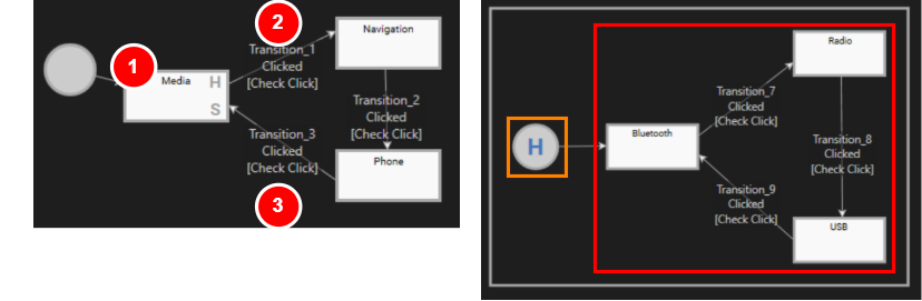
In the figure above, the State Machine diagram contains a Subchart "Media". withThe Subchart itself includes a History State isinstead placedof onan theInitial diagram.State.
- The
stateStatemachineMachine startsits transition fromat the Initial Stateonin thediagram,base diagram andthen movestransitions to the Subchart "Media" (see the left diagram1above). ItUpon entering the Subchart, it first passes through the History State (orange boxedarea in the above figure)area) and then enters the State loop (red boxedarea in the above figure)area), starting withStatethe "Bluetooth".state.- The state machine
will remainremains in this Subchart as long as transitions betweenBluetooth,Bluetooth,Radio,Radio, and USB are triggered. - When Transition_1
on(markedtheasdiagram (2 in thediagram above)figure) is triggered,thisthe Subchartwill exit.
When entering the Media statestate, asthe wellsystem asexecutes whenboth exitinglevels of OnEntry actions: the Media state,state's OnEnterOnEntry ofactions and the MediaOnEntry state as well as OnEnteractions of the stored most recently selected Media device state (Bluetooth/USB/Radio)e.g. willBluetooth, beUSB called.or Radio).
SeeFor an example implementation that demonstrates the use of a History State within a Subchart, see State Machine SolutionSolution. for a sample state machine solution using History State.
Note
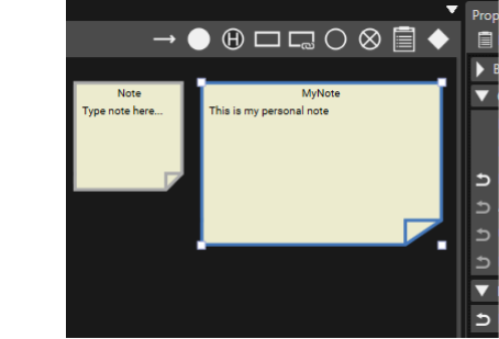
In athe State Machine Editor,Editor, you can add NoteNotes to the diagram to supplementprovide theadditional information.information, Thissuch helpsas youTODOs, caveats, implementation details or design considerations. Notes help improve clarity and make complex diagrams easier to visually organize the design contentunderstand and notes.maintain.
Choice
A Choice element allows you to branch Transitions.Transitions, Thisenabling makesthe itState easyMachine to editenter a specific state machines that define different behaviors based on the evaluation of multiple conditions. This feature simplifies the design and maintenance of complex logic where a set of conditions must be checked to determine the next state.
Example of Choice Usage
In the State Machine diagram below, the transition startsbegins fromat the Initial State on the diagram and transitionsproceeds to the Evaluate State.
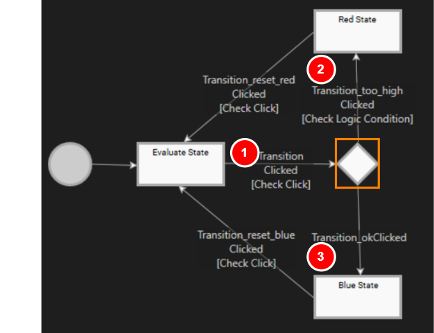
When the button is clicked in the Evaluate State, Transition"Transition" (marked as 1 in the above figure) is executed,triggered andby a mouse click, the transitionState Machine moves to the Choice element (orange frameorange-framed section in the abovefigure). figure),At wherethis point, the Transitiontransition branches.
- If the condition is
met:metTransition(value exceeds the threshold): The State Machine transition to "RedState" if the value is too largeState" (marked as 2 in theabovefigure).
The priority of aan Exit Transition (Exit Transition) connected to a Choice element is the same as the normal Transition priority change procedure.
By utilizing Choice,Choice elements, multiple conditions can be clearly organized within the stateState machine,Machine, making it easier to visually grasp the branching structure.structure easy to visualize. This makes it possible to design complex logic in a simple manner.
ViewState
ViewState is a dedicated State for controlling whether a specific View is shown or hidden within the state machine. It works with the View defined in the View Definition Editor and switches screens in sync with state transitions via the ActivateView action set in On Entry/On Exit Actions.
You can create a ViewState either from the State Machine Editor toolbar or by dragging and dropping a View from Solution Explorer onto the State Machine Editor diagram.
Create from a View
To create a new ViewState from a View in Solution Explorer:
-
In Solution Explorer, select any View.
-
Drag the selected View and drop it onto a blank area of the State Machine Editor diagram.
-
A new ViewState is placed on the diagram.
-
-
Assign an ActivateView action to both On Entry Actions and On Exit Actions of the created ViewState.
-
Configure the properties of the ActivateView action set on On Entry/On Exit Actions as described below.
These settings establish the basic flow in which this View is displayed while this State is active.Activate View On Entry Actions True Specify the view that was dropped. On Exit Actions False Specify the view that was dropped.
Place into an existing State/Subchart
To place a View inside an existing State or Subchart:
-
In Solution Explorer, select the target View.
-
Drag the View from Solution Explorer onto the State Machine Editor diagram and drop it on the State or Subchart you want to use as the transition source.
-
A new ViewState is placed inside the target State/Subchart.
-
A Transition from the containing State/Subchart to this ViewState is created automatically.
-
Its Condition is automatically set to Jump to View.
-
-
Assign an ActivateView action to both On Entry Actions and On Exit Actions of the ViewState.
-
Configure the properties of the ActivateView action set on On Entry/On Exit Actions as described below.
These settings let you configure a flow in which, when processing completes, the state machine transitions to the state that displays this View.Activate View On Entry Actions True Specify the view that was dropped. On Exit Actions False Specify the view that was dropped.