
Transitions configuration
This page describes how to set up transitions between the three States created in the previous operation. These state transitions can be configured in the State Machine Editor.
More information about state transitions can be found here.
State Transition Configuration
The Transition function of the State Machine Editor defines how and when the system moves from one state to another. Transitions are indicated by connecting two states with an arrow.
- Drag a State Transition from the State Machine Editor's top toolbar, and drop it onto the "Car_Cluster" State (Transition start side).
- A State Transition arrow is created, the tail of which is linked to the "Car_Cluster" State.
- The State Transition arrow's head can now be dragged across the diagram to define the target state.

- Drag the State Transition arrow's head onto the "Incoming_Call" State and attach it with a mouse-click.
- The two states, "Car_Cluster" and "Incoming_Call", are connected by a State Transition arrow.
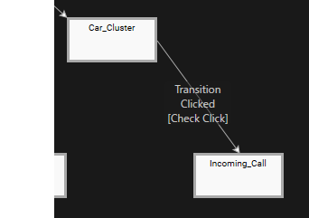
- The two states, "Car_Cluster" and "Incoming_Call", are connected by a State Transition arrow.
- Select the State Transition in the State Machine diagram and click the [Fusion...] button in the Behavior/Fusion Configuration Panel in the State Machine Editor's bottom left.
- Fusion will be opened, displaying the Transition's Fusion diagram.
- A Check Click Fusion node is connected to the Transition Fusion node's Condition connector.
- Fusion will be opened, displaying the Transition's Fusion diagram.
- Click on the Transition Fusion node's Actions connector.
- The [Select Behavior] dialog will be opened.
Instead of clicking on the Actions connector, you can click and drag the connector to a desired location in the diagram where the new Fusion node will be positioned.
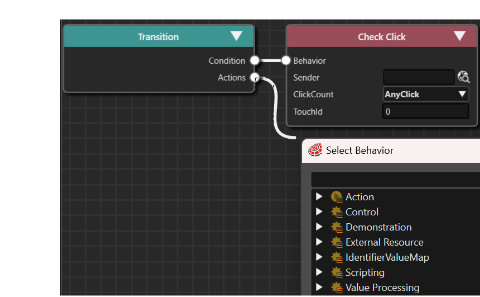
- The [Select Behavior] dialog will be opened.
- Enter "Transition Request" in the search field at the top of the dialog.
- While typing, the list of behaviors in the dialog will be narrowed down.
- While typing, the list of behaviors in the dialog will be narrowed down.
- Double-click [Action > Transition > Transition Request].
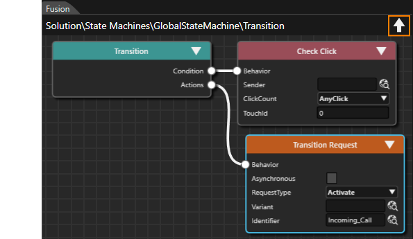
- A new Transition Request Fusion node will be created. It is linked to the Actions connector of the Transition Fusion node.
- A new Transition Request Fusion node will be created. It is linked to the Actions connector of the Transition Fusion node.
- Configure the Transition Request Fusion node according to the table below. The scene assigned to the property [Identifier] determines the destination of the transition.
- This operation completes the configuration of the transition from "Car_Cluster" to "Incoming_Call".
- Click the up arrow icon in the upper right corner of the Fusion panel to navigate back to the State Machine Editor.
Property Configuration RequestType Activate Identifier Solution > Scenes > Incoming_Call
- Repeat steps 1 through step 7 to configure the following five transitions.
- This finalizes the configuration of our State Transitions.
- Scene Car_Status is activated whenever State Car_Status is entered. Scene Car_Cluster is entered whenever State Car_Cluster is entered etc.
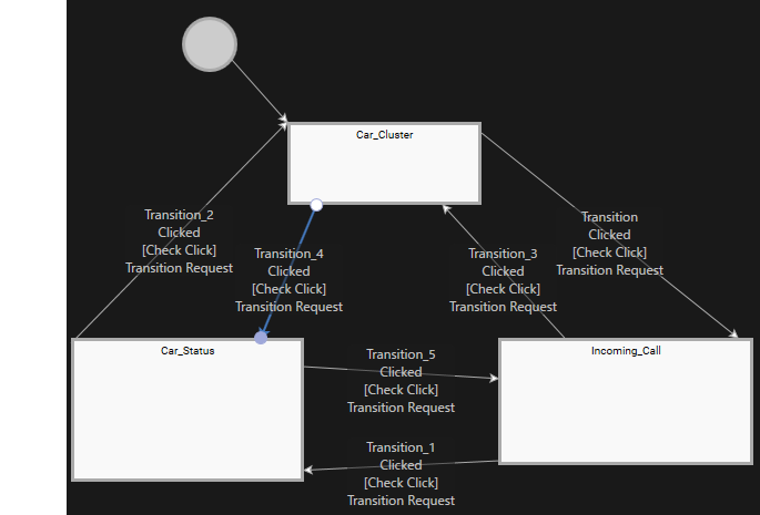
- The final State Machine diagram will look like the image shown below.
Transition RequestType Identifier From To Incoming_Call Car_Status Activate Solution>Scenes>Car_Status Car_Status Car_Cluster Activate Solution>Scenes>Car_Cluster Car_Cluster Car_Status Activate Solution>Scenes>Car_Status Car_Status Incoming_Call Activate Solution>Scenes>Incoming_Call Incoming_Call Car_Cluster Activate Solution>Scenes>Car_Cluster
Handle Control State
In the previous section, we configured the State Transitions and the activation of the respective scene. Next, we will define the conditions for triggering these transitions . Each State Transition has an attached "Check Click" Condition Behavior by default. In the following steps we will add a "Handle Control State" behavior to the TellTale controls "IndicatorLeft" and "IndicatorRight". This makes the Indicators behave like a control, enabling them e.g. to emit click events.
- In the Solution Explorer, navigate to [Solution > Scenes > Car_Cluster] and double-click the scene.
- The Scene Editor will be opened, displaying the scene "Car_Cluster".
- The Scene Tree panel will show the scene's scene tree.
- In the Scene Tree panel's right side, an extra scene tree is available, displaying the [Fusion...] button and the currently selected RenderNode's Behaviors and Effects.
- In the Scene Tree panel, expand the scene tree along the following path: Cluster > StatusTop > Telltales.
- The Group2D nodes Brake, AirBag, Engine, OpenDoors, IndicatorRight, and IndicatorLeft will be displayed.
To expand a Group2D node, you can either double-click it or you can single-click on the little triangle to it's left.
- The Group2D nodes Brake, AirBag, Engine, OpenDoors, IndicatorRight, and IndicatorLeft will be displayed.
- In the Scene Tree panel, select the IndicatorRight Group2D node, then click on the [Fusion...] button in the Extra Scene tree.
- Fusion will be opened, displaying the Fusion diagram of IndicatorRight.
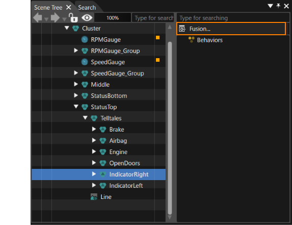
- Fusion will be opened, displaying the Fusion diagram of IndicatorRight.
- In Fusion, click the Behaviors connector on the IndicatorRight Fusion node.
- The [Select Behavior] dialog will be opened.
- The [Select Behavior] dialog will be opened.
- In the Select Behavior dialog, enter "Handle Control State" in the search field at the top.
- The list of behaviors in the dialog will be narrowed down to [Control > Internal > Handle Control State].
- The list of behaviors in the dialog will be narrowed down to [Control > Internal > Handle Control State].
- Double-click the "Handle Control State".
- A Handle Control State Fusion node will be linked to the IndicatorRight Fusion node.
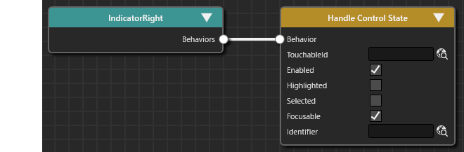
- A Handle Control State Fusion node will be linked to the IndicatorRight Fusion node.
- Perform steps 3 through 6 for "IndicatorLeft" as well.
- IndicatorLeft and IndicatorRight are now behaving like controls. They are e.g. able to emit click events.
- IndicatorLeft and IndicatorRight are now behaving like controls. They are e.g. able to emit click events.
- Repeat steps 1 through 7 for scenes "Car_Status" and "Incoming_Call", adding Handle Control State behaviors to their IndicatorLeft and IndicatorRight component in the same manner.
With the configurations above, IndicatorLeft and IndicatorRight are configured to behave like a control. They are e.g. able to emit click events.
Conditions for the State Transitions
Finally, each State Transition's 'Check Click Condition Behavior' has to be configured with a sender - the control that emits the click event. We have set up IndicatorLeft and IndicatorRight to send click events, so they can be configured as senders.
- In the State Machine Editor, select the state transition from "Car_Cluster" to "Incoming_Call".
- Click the [Fusion...] button in the lower left of the State Machine Editor .
- Fusion will be opened, displaying the Fusion diagram of the selected state transition.
- The Transition Fusion node's Condition connector is linked to the Check Click Fusion node.
- Fusion will be opened, displaying the Fusion diagram of the selected state transition.
- In Fusion at the Check Click Fusion node, click the 'Select item' icon to the right of the [Sender] property.
- The [Choose Item] dialog will be opened.
- The [Choose Item] dialog will be opened.
- In the Choose Item dialog, navigate to and select [Solution > Car_Cluster > Cluster > StatusTop > IndicatorRight], then click [OK].
- IndicationRight will be displayed in the Sender property of Check Click.
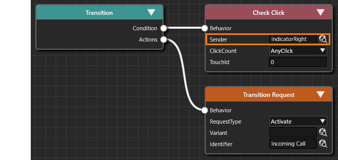
- IndicationRight will be displayed in the Sender property of Check Click.
- Click the up arrow icon located in the upper-right corner of the Fusion panel.
- The State Machine Editor panel will be opened, displaying the State Machine diagram.
- The State Machine Editor panel will be opened, displaying the State Machine diagram.
- Repeat steps 1 through 5 to configure the sender property for the remaining Check Click Condition behaviors, applying the configurations from the table
below.below.- All state transitions are now configured correctly.
Transition Check Click > Sender From To Incoming_Call Car_Status Incoming_Call > ... >IndicatorRight Car_Status Car_Cluster Car_Status > ... > IndicatorRight Car_Cluster Car_Status Car_Cluster > ... > IndicatorLeft Car_Status Incoming_Call Car_Status > ... > IndicatorLeft Incoming_Call Car_Cluster Incoming_Call > ... > IndicatorLeft
- All state transitions are now configured correctly.
This completes the setup of the state transitions triggered by click events emitted by a control, which then leads to an activation of a new scene. InOn the next chapter,page, we will confirm the functionality of our configuration.