
Transitions configuration
SetThis page describes how to set up transitions between the three States created in the previous operation. InThese state transitions can be configured in the State Machine Editor,Editor.
More information about state transitions arecan setbe usingfound Transitions. This transition consists of a Sender, Condition, and Action. Therefore, if the set Condition is evaluated as "true," the set Action is executed.here.
State Transition ConfigurationsConfiguration
The Transition function of the State Machine Editor isdefines usedhow and when the system moves from one state to set up transitions between states.another. Transitions are indicated by connecting eachtwo statestates with an arrow.
- Drag a State Transition from the
toolbarStateinMachinetheEditor'suppertopright corner of the state machine editor,toolbar, and droptheitdraggedontotransition intothe "Car_Cluster" State (Transition start side).- A State Transition
(arrow)arrowappearsisoncreated, thestatetailmachineofeditor andwhich isinlinkedatodraggingthe "Car_Cluster" State.
- A State Transition
- The State Transition arrow's head can now be dragged across the diagram to define the target state.


ExtendDrag the State Transition(arrow)arrow'stohead onto the "Incoming_Call" State(Transition end side)and attach it with a mouse-click.
- The two states, "Car_Cluster" and "Incoming_Call", are connected by
arrows.a State Transition arrow.

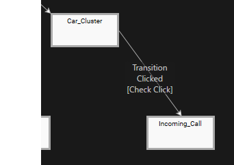
- The two states, "Car_Cluster" and "Incoming_Call", are connected by
WithSelect the State Transitionselected, from the lower left ofin the State MachineEditordiagrampanel,and click the [].The panel will switch to the Fusion panel and the Fusion diagram for the Transition will be displayed.
A Check Click Fusion node is connected to the
- The [
Behavior ]Behavior] dialog willappear.
be opened.Instead of clicking on the Actions connector, you can click and drag the connector to a desired location in the diagram where the new Fusion node will be positioned.

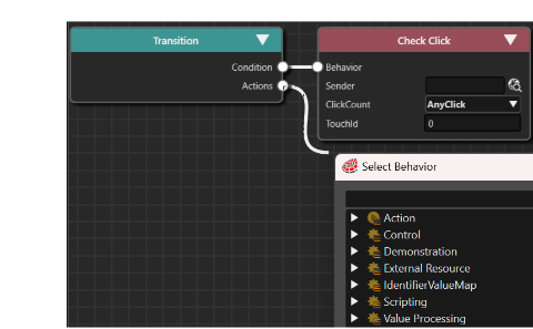
TheWhile typing, the list of behaviors in the dialog will be narroweddown to [ Action>Transition>Transition Request ].down.
TheA new Transition Request Fusion node will be created. It is linked to the Actions connector of the Transition Fusion node.
node
- This operation completes the configuration of the transition
settingsfrom "Car_Cluster" to "Incoming_Call". - Click the up arrow icon in the upper right corner of the Fusion panel to
switchnavigatethebackdisplayto the State Machine Editor.
Property Configuration RequestType Activate Identifier Solution > Scenes > Incoming_Call

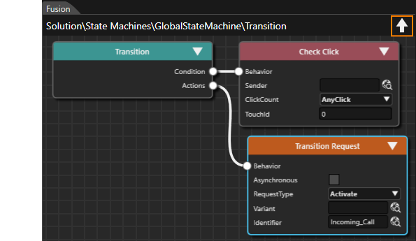
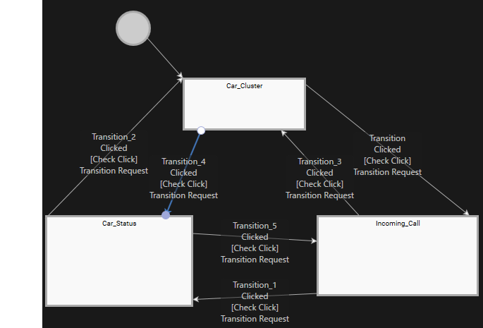
AllThisRequestTypefinalizes the configuration of our State Transitions.
the image shown below.
| Transition | RequestType | |

Handle Control State
In the previous section, youwe used Transition to setconfigured the transitionState betweenTransitions eachand the activation of the respective scene. Next, youwe will setdefine the conditions underfor whichtriggering these transitions occur.. TheEach State Transition you added has aan Conditionattached behavior called "Check Click" initiallyCondition set.Behavior Therefore,by default. In the following steps we will add a "Handle Control State" is addedbehavior to the targetTellTale nodecontrols in"IndicatorLeft" orderand "IndicatorRight". This makes the Indicators behave like a control, enabling them e.g. to sendemit stateclick events from each scene as triggers to this Condition behavior.events.
FromIn the Solution Explorer, navigate to [Solution > Scenes > Car_Cluster] and double-click[theScenes>Car_Cluster ].scene."Car_Cluster"The Scene Editor willappearbeinopened, displaying the scene "Car_Cluster".
- The Scene Tree panel will show the scene's scene tree.
AnIn the Scene Tree panel's right side, an extra scene treewillisappearavailable,todisplaying theright[Fusion...]ofbutton and thescenecurrentlytree.selected RenderNode's Behaviors and Effects.ClickInonthe[SceneCluster>StatusTop>TelltalesTree]panel,inexpand the scene treetoalongexpandtheit.following path: Cluster > StatusTop > Telltales.
- The
groupGroup2D nodes Brake, AirBag, Engine, OpenDoors, IndicatorRight, and IndicatorLeft will be displayed.To expand a Group2D node, you can either double-click it or you can single-click on the little triangle to it's left.
- The
ClickInonthe Scene Tree panel, select the IndicatorRightgroupGroup2Dnodenode,andthen click on the [Switch to theFusionpanelwillandbe opened, displaying the Fusion diagram of IndicatorRightwill be displayed..

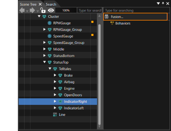
DragInandFusion,moveclick themouse over theBehaviors connector on theright side of theIndicatorRight Fusionnode in the Fusion diagram and release left click anywhere.node.- The [
Behavior ]Behavior] dialog willappear.be opened.
- The [
EnterIn the Select Behavior dialog, enter "Handle ControlstateState" in the search field at thetop of the dialog.top.- The list of behaviors in the dialog will be narrowed down to [
state ]State].
- The list of behaviors in the dialog will be narrowed down to [
- Double-click the "Handle Control
state"State".- A Handle Control
stateState Fusion node will be linked to theIndicatorLeftIndicatorRight Fusion node.

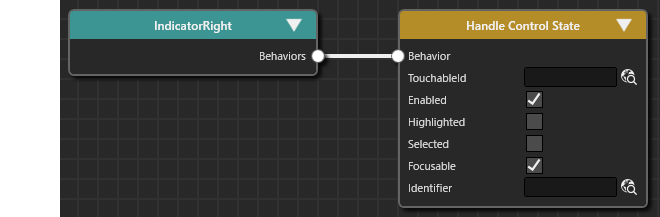
- A Handle Control
- Perform
the stepsteps 3 throughstep6abovefor "IndicatorLeft" as well.TheIndicatorLeftsameandsettingsIndicatorRight aremadenow behaving like controls. They are e.g. able to emit click events.
With the above settings, State events are sent to Condition "Check Click" as State conditions.
Transition Conditions
Finally, to connect the event destination of theadding Handle Control State behaviors to thetheir Condition,IndicatorLeft theand configurationIndicatorRight work is donecomponent in the same manner.
With the configurations above, IndicatorLeft and IndicatorRight are configured to behave like a control. They are e.g. able to emit click events.
Conditions for the State MachineTransitions
Finally, each State Transition's 'Check Click Condition Behavior' has to be configured with a sender - the control that emits the click event. We have set up IndicatorLeft and IndicatorRight to send click events, so they can be configured as senders.
OnIn the State Machine Editor, selectTransitionthe state transition from "Car_Cluster" to "Incoming_Call".WithClickTransitiontheselected,[Fusion...]frombutton in the lower left of the State Machine Editorpanel, click [ Fusion... ].TheFusionpanelwillswitchbetoopened,thedisplayingFusion panel andthe Fusion diagramforof theTransitionselectedwillstatebe displayed.transition.- The
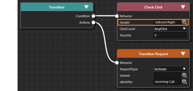
connector (Condition) in the upper right corner of theTransition Fusionnodenode's Condition connector isconnectedlinked to the Check Click Fusion node.
ClickIn Fusion at the Check Click Fusion node, click the 'Selectitemitem' icon to the right of the [Sender]Sender ] in the Check Click Fusion node.property.- The [
Item ]Item] dialog willappear.be opened.
- The [
SelectIn theIndicatorRightChoosenodeItemofdialog,thenavigatescenetothatandwillselectbe the source of the screen transition from[Solutionthe>listCar_Clusteron>theClusterleft>sideStatusTopof>the dialogIndicatorRight],andthenpress theclick [OK ] button in the dialog.OK].In this case, select [ Solution>Car_Cluster>Cluster>StatusTop>IndicatorRight ].- IndicationRight will
appearbe displayed in the Sender property of Check Click.

- Click
onthe up arrow icon located in theupperupper-right corner of the Fusion panel.- The
displayStateswitchesMachinefrom the FusionEditor paneltowill be opened, displaying the State MachineEditor panel.diagram.
- The
- Repeat steps 1 through 5 to configure the
abovesenderoperationproperty forothertheinterstateremainingtransitionsChecktoClicksetCondition behaviors, applying theSender.configurations from the table below.SpecifyAllIndicatorRight for clockwisestate transitionsandareIndicatorLeftnowforconfiguredcounterclockwise transitions.correctly.
Check Click > Sender From ToTransition
Incoming_CalltoCar_Status Incoming_Call > ... >IndicatorRight Car_StatustoCar_Cluster Car_Status > ... > IndicatorRight Car_ClustertoCar_Status Car_Cluster > ... > IndicatorLeft Car_StatustoIncoming_Call Car_Status > ... > IndicatorLeft Incoming_CalltoCar_Cluster Incoming_Call > ... > IndicatorLeft
The above stepsThis completes the setup for executing transitions between States based on triggers and events received from the scene. Confirmation of the state transitions settingtriggered onby thisclick pageevents willemitted beby performeda oncontrol, which then leads to an activation of a new scene. In the next page.chapter, we will confirm the functionality of our configuration.