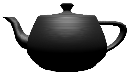
Single Pass Effects in Candera > Examples for 3D Effect Shaders
Description
This chapter describes special 3D effect shaders techniques supported by Candera.
Chapters
Bump Mapping
Description
This chapter briefly describes bump mapping techniques supported by Candera.
Sub Chapters
Introduction
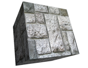
Bump mapping is a technique in computer graphics for simulating bumps and wrinkles on the surface of an object.
This is achieved by perturbing the surface normals of the object and using the perturbed normal during lighting calculations. The result is an apparently bumpy surface rather than a smooth surface although the surface of the underlying object is not actually changed.

Workflow
Inventory
In order to generate the bump mapping effect on a surface you need:
- A mesh
- A specific shader
- A shader parameter setter
- A normal map texture
- A color map texture
- A material
Mesh
Any mesh can be used for this purpose but the mesh vertex buffer has to contain also the tangents and the binormals vertex attributes. This information can be added to the vertex buffer in the 3D content creation tool (3DS Max, Blender, etc.), before exporting the FBX, or, at run time, using the Candera::Math3D::CreateTangentsAndBinormalsFromVertexBuffer function as shown below:
mesh->SetVertexBuffer(Math3D::CreateTangentsAndBinormalsFromVertexBuffer(mesh->GetVertexBuffer()));
Shader
Use the shader from table below:
| Vertex shader | RefTransLight1BumpMap |
| Fragment shader | RefLight1BumpMap |
Set the appearance shader for the mesh:
mesh->GetAppearance()->SetShader(bumpmapShader);
Shader Parameter Setter
The uniform setter will have to be set as follows:
    shaderParamSetter->SetModelMatrix4Enabled(true);
    shaderParamSetter->SetNormalModelMatrix3Enabled(true);
    shaderParamSetter->SetModelViewProjectionMatrix4Enabled(true);
    shaderParamSetter->SetLightActivationEnabled(true);
    shaderParamSetter->SetMaterialActivationEnabled(true);
    shaderParamSetter->SetTextureActivationEnabled(true);
    shaderParamSetter->SetLightsCoordinateSpace(Light::World);
    shaderParamSetter->SetCameraPositionEnabled(true);
    mesh->GetAppearance()->SetShaderParamSetter(shaderParamSetter);
Color Texture
The color texture applies an image to the surface of a mesh. This texture should be set on the mesh with texture unit 0.
Add the color texture to the appearance:
mesh->GetAppearance()->SetTexture(colorTexture, 0);
Normal Map Texture
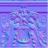
The normal map images store the direction of normals directly in the RGB values of an image. These normals are used for lighting calculation instead of the vertices normals. Normal maps are generated using special graphics software usually from a higher resolution geometry than the geometry you're applying the map to.[1]

Add the normal map texture to the appearance:
mesh->GetAppearance()->SetTexture(normalMapTexture, 1);
Material Configuration
        mesh->GetAppearance()->GetMaterial()->SetAmbient(Color(0.3f, 0.3f, 0.3f, 1.0f));
        mesh->GetAppearance()->GetMaterial()->SetEmissive(Color(0.0f, 0.0f, 0.0f, 1.0f));
        mesh->GetAppearance()->GetMaterial()->SetDiffuse(Color(1.0f, 1.0f, 1.0f, 1.0f));
        mesh->GetAppearance()->GetMaterial()->SetSpecular(Color(1.0f, 1.0f, 1.0f, 1.0f));
        mesh->GetAppearance()->GetMaterial()->SetSpecularPower(40.0f);
Examples
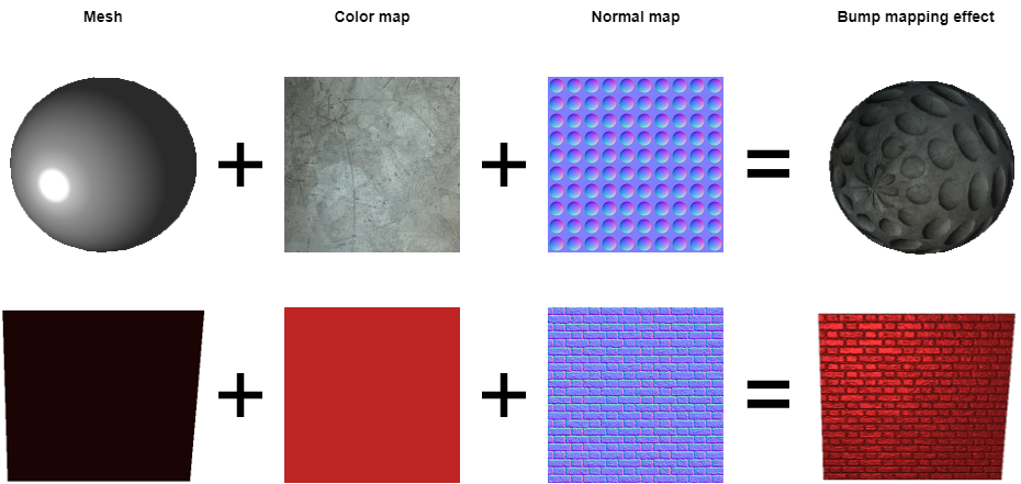
Here is exemplified the bump map effect applied on two meshes:

Bump Mapping in SceneComposer
To experiment with Bump mapping in Scene Compose use the solution ShaderExamples from the folder cgi_studio_player/content/Tutorials/04_ShaderUsage.
References
The pictures from this tutorial where obtained from the following sources:
[1] http://planetpixelemporium.com/tutorialpages/normal3.html
Procedural Textures
Description
This chapter briefly describes the procedural wood technique supported by Candera.
Sub Chapters
Introduction
Procedural Wood
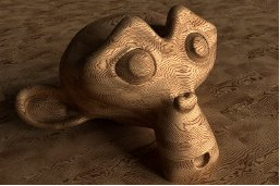
Procedural wood is texturing technique which generates an on-the-fly texture using an algorithm that creates a wood realistic 3D representation. The algorithm will generate concentric rings colored alternatively with two colors which, if chosen rightly, will show a wood-like appearance. The effect can be controlled by setting the uniforms:
- u_CustomWoodCenter - rings center position
- u_CustomWoodColor1 - even rings color
- u_CustomWoodColor2 - odd rings color

Workflow
Inventory
In order to generate the wood effect on a mesh all you need to do is to configure the material, an appropriate shader and a shader parameter setter for its appearance.
Shader
The table below presents the vertex and fragment shader which generates the wood effect:
| Vertex shader | RefTransLight1ProceduralWood |
| Fragment shader | RefProceduralWood |
Set the appearance shader for the mesh:
mesh->GetAppearance()->SetShader(woodShader);
Shader Parameter Setter
The uniforms setter will have to be configured as follows:
        woodShaderParamSetter->SetModelViewProjectionMatrix4Enabled(true);
        woodShaderParamSetter->SetLightActivationEnabled(true);
        woodShaderParamSetter->SetMaterialActivationEnabled(true);
        woodShaderParamSetter->SetTextureActivationEnabled(true);

        mesh->GetAppearance()->SetShaderParamSetter(woodShaderParamSetter);
Prepare the uniforms data:
        Float woodCenter[] = { 0.0f, 0.0f, 0.2f};
        Float woodColor1[] = { 0.81f, 0.63f, 0.41f, 1.0f };
        Float woodColor2[] = { 0.56f, 0.27f, 0.12f, 1.0f };
        Float woodMultiplier = 100.0f;
Set the uniforms using the shader parameter setter:
        woodShaderParamSetter->SetUniform("u_CustomWoodCenter", Shader::FloatVec3, woodCenter);
        woodShaderParamSetter->SetUniform("u_CustomWoodColor1", Shader::FloatVec4, woodColor1);
        woodShaderParamSetter->SetUniform("u_CustomWoodColor2", Shader::FloatVec4, woodColor2);
        woodShaderParamSetter->SetUniform("u_CustomWoodMultiplier", Shader::Float, &woodMultiplier);
Material Configuration
        mesh->GetAppearance()->GetMaterial()->SetAmbient(Color(0.0f, 0.0f, 0.0f, 1.0f));
        mesh->GetAppearance()->GetMaterial()->SetEmissive(Color(0.0f, 0.0f, 0.0f, 1.0f));
        mesh->GetAppearance()->GetMaterial()->SetDiffuse(Color(1.0f, 1.0f, 1.0f, 1.0f));
        mesh->GetAppearance()->GetMaterial()->SetSpecular(Color(1.0f, 1.0f, 1.0f, 1.0f));
        mesh->GetAppearance()->GetMaterial()->SetSpecularPower(40.0f);
Examples
Here is exemplified the wood effect applied on two meshes:
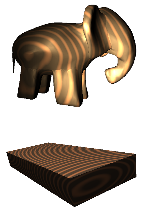

Wood Effect in SceneComposer
To experiment with the procedural wood technique in SceneComposer use solution ShaderExamples from folder cgi_studio_player/content/Tutorials/04_ShaderUsage.
References
[1] Image taken from http://blenderartists.org/forum/showthread.php?246113-A-fine-procedural-wood-material-for-Cycles
Environment Mapping
Description
This chapter describes the environment mapping techniques supported by Candera.
Environment mapping is an image based technique to achieve an appearance of reflecting object surface. A texture is used to show the environment as a reflection.
Sub Chapters
Sphere Map
Description
This chapter describes the sphere mapping techniques supported by Candera.
Sphere mapping was the first environment mapping technique where the reflective environment is mapped onto a single texture as it would be reflected by a mirror ball. Sphere mapping is suitable on concave surfaces while else Cube mapping achieves better results.
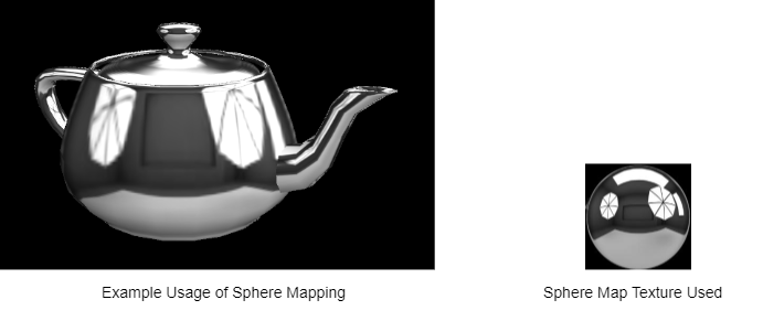

SphereMap in SceneComposer
To experiment with the sphere mapping technique in SceneComposer use solution ShaderExamples from folder cgi_studio_player/content/Tutorials/04_ShaderUsage.
Cube Map
Description
This chapter describes the cube mapping techniques supported by Candera.
Cube mapping is a rendering technique whereby six bitmaps are mapped to the sides of a cube, to produce environment mapping effects, such as reflections, or a skybox background. Unlike the old sphere mapping technique, cube map images do not need to be distorted to match the current view-angle, and is therefore a more efficient and flexible method to achieve reflections. However, in OpenGL ES 2.0, any texture filtering is applied separately to the six individual images, which may cause rendering artifacts along the image borders. This issue was corrected in OpenGL ES 3.0, which provides seamless cubemap filtering. There is nothing you need to do to enable seamless cubemap filtering. All linear filter kernels will automatically use it, when targeting OpenGL ES 3.0.
A special application for cube mapping is the Skybox.
CubeMap in SceneComposer
To experiment with CubeMap in SceneComposer, use solution ShaderExamples from folder cgi_studio_player/content/Tutorials/04_ShaderUsage.
SkyBox
Description
This chapter describes the skybox technique supported by Candera.
SkyBox was implemented to support cubic panorama backgrounds ("SkyBoxes"). A Skybox displays the background environment of a scene, by using a world-space axis-aligned cube, with six images assigned to the faces of the cube. This cube is centered on the active camera's current position, which creates the illusion that the background image is infinitely far away. The skybox is rendered before any other nodes, with depth writing and testing turned off, to ensure that it appears behind all other nodes in the scene.
In OpenGL ES 2.0, linear filtering is applied separately to the six images, which may cause rendering artifacts (seams) along the cube edges. In OpenGL ES 3.0, this minor defect was corrected, by applying filtering across image borders, to create seamless cubemaps. No action is required to enable seamless cubemaps under OpenGL ES 3.0. However, this feature is not available in OpenGL ES 2.0 or its extensions.
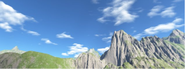

SkyBox in SceneComposer
To experiment with SkyBox in SceneComposer use solution ShaderExamples from folder cgi_studio_player/content/Tutorials/04_ShaderUsage.
Reflection & Refraction
Description
This chapter describes the reflection and refraction techniques supported by Candera.
Candera uses new shaders to achieve reflection and refraction appearances:
- RefTransCubeMapReflection.vert
- RefTransCubeMapRefraction.vert
- RefTransCubeMapReflectionRefraction.vert
- RefCubeMapTex.frag
- RefCubeMapTex2.frag
These shaders demonstrate how environment mapping reflections, refraction and the combination of both can be realized using CubeMap textures. The combined reflection and refraction shading results in a glass effect especially when combined with a skybox using the same cubemap textures
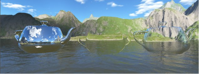

Reflection and Refraction in SceneComposer
To experiment with Reflection and Refraction in SceneComposer use solution ShaderExamples from folder cgi_studio_player/content/Tutorials/04_ShaderUsage.
Anisotropic Lighting
Description
This chapter briefly describes the anisotropic lighting technique supported by Candera.
Sub Chapters
Introduction
Anisotropic Lighting
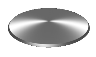
The Candera implementation of the anisotropic lighting model can be used to generate the effect of a surface having grooves or fine directional grain like, for instance, brushed metal, shiny side of a CD, vinyl records etc.
The effect can be configured by setting the uniforms:
- u_AlphaU - distribution of specular light component in U direction
- u_AlphaV - distribution of specular light component in V direction

Workflow
Inventory
In order to generate the brushed metal effect on a mesh you need to configure the material, a texture, an appropriate shader and a shader parameters setter for its appearance.
Shader
The table below presents the vertex and fragment shader which generates the brushed metal effect:
| Vertex shader | RefTransAnisotropicLight1 |
| Fragment shader | RefAnisotropicLight1SpecularTex |
Set the appearance shader for the mesh:
mesh->GetAppearance()->SetShader(anisotropicLightingShader);
Shader Parameter Setter
The uniforms setter will have to be configured as follows:
       m_anisotropicLightSetter->SetModelMatrix4Enabled(true);
       m_anisotropicLightSetter->SetNormalModelMatrix3Enabled(true);
       m_anisotropicLightSetter->SetModelViewProjectionMatrix4Enabled(true);
       m_anisotropicLightSetter->SetCameraPositionEnabled(true);
       m_anisotropicLightSetter->SetLightActivationEnabled(true);
       m_anisotropicLightSetter->SetMaterialActivationEnabled(true);
       m_anisotropicLightSetter->SetTextureActivationEnabled(true);
       m_anisotropicLightSetter->SetLightsCoordinateSpace(Light::World);

       mesh->GetAppearance()->SetShaderParamSetter(m_anisotropicLightSetter);
Prepare the uniforms data:
       Float m_alphaU = 0.28f;
       Float m_alphaV = 0.23f;
You can generate other effects like plastic laminate, glossy grey paper, rolled aluminium etc. by simply changing the values for m_alphaU, m_alphaV and the diffuse and specular colors for the material.
Set the uniforms using the shader parameters setter:
       m_anisotropicLightSetter->SetUniform("u_AlphaU", Shader::Float, &m_alphaU);
       m_anisotropicLightSetter->SetUniform("u_AlphaV", Shader::Float, &m_alphaV);
Material Configuration
       mesh->GetAppearance()->GetMaterial()->SetAmbient(Color(0.0f, 0.0f, 0.0f, 1.0f));
       mesh->GetAppearance()->GetMaterial()->SetEmissive(Color(0.0f, 0.0f, 0.0f, 1.0f));
       mesh->GetAppearance()->GetMaterial()->SetDiffuse(Color(0.4f, 0.4f, 0.4f, 0.4f));
       mesh->GetAppearance()->GetMaterial()->SetSpecular(Color(1.0f, 1.0f, 1.0f, 1.0f));
       mesh->GetAppearance()->GetMaterial()->SetSpecularPower(40.0f);
Texture

Set the appearance texture:
mesh->GetAppearance()->SetTexture(texture, 0);
Example
The picture below shows the final result after setting the mesh appearance as described above: