GettingStartedControls Part 2
Part
2 of the GettingStartedControls Tutorial covers the creation of a scene for climate control using various predefinedClimate Scene
Composer controls. As basis for part 2 of our GettingStartedControls creation tutorial please use your own created solution from part 1.
TheOur final result of our ClimateControl Scenescene will look like this:
Please
Preparing the Climate Scene
Createcreate a new scene
viausing the
menuScene "Scene" -menu's "New 2D
Scene"Scene…" ormenu pressitem.
<
"Add
New Scene 2D" dialog will be opened.
InName the firstnew row select "/Scenes" from the drop-down menu. Enterscene "SceneClimate" as name and press [OK]. We always use the prefix "Scene" to have all scenes listed nextnear to each other in the Solution Explorer panel.view.
The scene "SceneClimate"is isnow created and visible in the Solution Explorer panel in folder "Scenes".
The new scene isalready opened
in the Scene Editor and ininside the Scene Tree panel.
InIt already contains a standard camera. The Viewport size of the
Scenecamera Treeis panel you can see thatusing the
scenesize alreadyof hasthe aRender camera.Target In(1024x768). The new scene's camera should automatically connect to the Render Target. If it isn't, please drag the Camera under the Render Target in the Render Targets
panel you can see that the camera is already added to the RenderTarget.
panel.
In the Render Targets panel check the checkbox of "SceneClimate\Camera" in order to enable rendering.
In the Render Targets panel select the SceneClimate\Camera. In the Properties panel's [ Camera ] section change the sequence number to 1.
The camera's sequence number is set to 1.
In the Scene Tree panel the red Information/Warning/Error square disappears.
Before dragging the ClimateScene'snew Camera of SceneClimate, the RenderTarget setup looks like this:
After dragging and dropping, please check the checkbox in front of the SceneClimate/Camera(0) entry to enable rendering.
Setting up the Climate Scene Layout
For the climate scene we will use a more realistic setup of the scene than before, because very often the layout of the elements of a scene are dependent to the screen size or language. Some languages for example are written from right to left and others from left to right. This for sure will influence the layout of texts and controls.
InsteadProbably the easiest layout mechanism to use is the grid layout control. You can find the grid layout in the toolbox in the group of absolute"Nodes positioning2D". ofIt all elements, we will use a GridLayout.
Inis the
Toolboxicon panelwith underthe [9 Nodessquares 2Das ]shown dragbelow.
and
Drag the grid layout into the Scene Editor panel or into the Scene Tree panel on the SceneClimate node.
The Aonly GridLayoutdifference of both actions is, that dragging into the Editor is
visiblesetting the last mouse position as the position of the grid layout. But this can be adapted easily. Open the context menu of the grid using the right mouse button on top of the node in the Scene Tree panel.
It is also available in the Scene Editor, but only its pivot point is visible when it is selected.
In the Scene Tree panel right-click on the GridLayout to open the context menu and chooseChoose "Configure Layouter..."
.
A new dialog is shown which helps in configuration of the GridLayoutgrid canlayout becontrol. configured.Use
this
On the Grid Layout Editor's lower left corner, use the [ + ] buttonsdialog to
add rows and columns (see image below). Configureconfigure 6 rows and 4 columns.
There are buttons at the bottom to add or delete rows/columns.
You can now see a rough grid layout. The GridLayoutnumbers ison configured with 6 rowstop and 4 columns.
Configureon the
columns'right widthsside can be used to define the width of the colums and the
rows'height heightsof accordingthe rows. You can either use numbers greater than 1 as direct pixel sizes or you can use numbers between 0 and 1 to
thedefine tableratios. belowSee usingLayouter.
We use the inputfirst and last column as free space for aesthetic reasons. The second column will be used for text descriptions and the third column for the controls to change settings. Therefore, enter into the edit fields on top of the topgrid and(0.05 right./
0.3 Rows/ and0.5 columns/ are0.05). configuredFor all rows please fill in 0.2 as in the image above.
Press OK to Column
Width
Row
Width
Column 1
0.05
Row 1
0.20
Column 2
0.30
Row 2
0.20
Column 3
0.50
Row 3
0.20
Column 4
0.05
Row 4
0.20
Row 5
0.20
Row 6
0.20
When you're done configuring, pressclose the
[OK]dialog.
button.In
the The Grid LayoutScene Editor
will be closed.
Be aware that you cannot see the GridLayout.grid Itsuntil sizenow, isbecause 0the asgrid long ashas no sizecontent. Let us create dummy content to better understand and no content for its cells has been configured.
Insee the
Propertiesgrid. panel'sDrag [a TransformationsSolid ]Color sectionNode configurefrom the
followingToolbox positionon of the GridLayout.
The positiontop of the GridLayout
node in the Scene
EditorTree hasPanel.
changed.
Target
Item
Setting
Value
Position
X
0
Insee the Propertiesfirst panel's(top [left) Transformationscell ]of sectionyour configuregrid. To be able to see all 24 cells we need additional 23 Solid Color Nodes. We will create this using the followingmulti sizeclone function accessible via the context menu of the GridLayout.Solid Color Node.
Switch to the Multiple Clone tab and enter 23 into the Number of Copies field. Press OK.
The Editor panel looks now like this:
And the Scene Tree panel looks like this:
Go back into the Configure Layouter dialog via the context menu.
As you can see, all of the nodes have a warning symbol. This is because all nodes are sharing one single cell. To automatically spread the SolidColorNodes into different cells press the Apply default arrangement button. You can also do it by hand with dragging and dropping the nodes from the left list into the cells.
After pressing OK your Editor should contain something like this:
As mentioned earlier we have to position the grid into its scene. Therefore change the grid's position to (0/0).
And change its size to 1024x714. The size is currently calculated automatically. In order to be able to change the values for the size, you have to click on the [ A ] button to disable the automatic calculation of the size.
You
can now Thesee sizethe structure of
theour GridLayoutscene. has changed.
The GridLayout's grid is now visible.
Target Item
Setting Value
Size X
1024
Size Y
714
It is recommended toPlease save
theyour Scenescene Composer solution.
now.
Creating and Configuring the Labels
Each of the Controls inAdding the Climate Control Scene hasContent
To put real content into our scene, import a label,few tellingimages by clicking (Import > Import Images) and selecting the userimages whichin setting/cgi_studio_content/Resources/GettingStartedControls/Climate:
he
Let us start with it.
the
texts Fromneeded for our Climate scene. Use the Text controls from the Toolbox panel
drag(Controls - Common - Text) to place the following texts:
To set the text itself please edit the Control property, "Text". We are using a smaller font than the default one. Please choose OpenSansRegular25.
For the Steering heater text we adapt the settings to be able to use multiple lines. Check the "Multiline" property.
Repeat editing the texts and droptext astyles "for all of the listed texts. Also, you can press Shift and click all the text controls, and then set the VerticalAlignment of these texts into VCenter, all at once.
Please instantiate the following controls by dragging from the Toolbox to the SceneClimate root node:
1 Slider (for temperature)
4 Buttons (2 for slider, 2 for off and max button for fan)
1 Text
" controlValue (for temperature)
1 CheckBox (for steering heater)
1 GroupBox (for air condition radio buttons)
2 RadioButtons (as group box content)
2 MultiStateButtons (for fan and seat heater)
1 SpinBox (for heating)
2 GridLayouts (for slider and fan elements)
1 StackLayout
Before structuring the Scene Tree, we rename the controls accordingly:
Now it's time to restructure the controls.
The following Radio Buttons will be placed inside the Stack Layout:
RadioButton_AC On
RadioButton_AC Off
And the StackLayout itself will be dragged into the Scenecontent Treeanchor panelof directlygroup box GroupBox_AC.
The controls for temperature adjustments will be dragged into the GridLayout_Slider:
Slider_Temperature
Text Value
Button_TempDec
Button_TempInc
The elements for the fan will be dragged into the GridLayout_Fan:
MultiStateButton_Fan
Button_Fan Max
Button_Fan Off
We will now remove all Solid Color Nodes and fill the GridLayout with our new controls.
Select all SolidColor Nodes and press the Delete key or use the context menu to delete them. Confirm deleting the SolidColorNodes in the delete items dialog with OK.
Drag all new items onto the "GridLayout" node. The "Text"resulting controlscene cantree bestructure foundwill inlook like this:
Drag the elements to their positions.
The "Text"result Controlshould canlook be seenlike in the Scene Editor'sEditor:
top
Setting up the SceneTreeTemperature panel,Controls
hierarchicallyAs orderedyou can see, the structure of the climate scene can be roughly recognized. However, we need to layout the elements carefully.
We start with the GridLayout_Slider. Configure the GridLayout as below theusing GridLayout.
"Configure Layouter…"
Infrom the
Propertiescontext panel'smenu:
[
Set the "Format Text" property of the Text Value under GridLayout_Slider to %2.1f °C, and the "HorizontalAlignment" property to "HCenter".
For the Slider_Temperature, set the following properties:
To adjust the images (Normal Image and Pressed Image) of Button_TempDec press the magnifying glass icon nexton the right of the property and select the correct image from the imported SceneClimate images as below:
Do the same for Button_TempInc, but using the corresponding "TempIncrease" images:
Next, we will configure the images for Slider_Temperature as below:
The slider's TextValue Control is supposed to display the value that is set via the slider. To add this functionality we need to drag a ForwardValue Behavior from the Toolbox to the Slider_Temperature in the Scene Tree Panel.
The Slider_Temperature's value needs to be forwarded to the TextValue control. Therefore, we need to set the ForwardValue Behavior's "TargetNode" property to the "Text Style"Value". property.
The "Text Style Palette" dialog will be opened displaying a list of text styles. The currently configured "OpenSans35" is selected.
In this "Text Style Palette" dialog select "OpenSans25" and click [OK]
InClick the
Scenemagnifying Editorglass the size of the "Text" control's text has decreased.
In the Scene Tree right-click on the "Text" control to open the context menu and select "Clone".
The "Clone Item" dialog is opened.
In the "Clone Item" dialog set the "Number of Copies" to 5 and click [OK].
In the Scene Tree panel you can see that 5 new "Text" controls have been added, named "Text_1", "Text_2" ...
In the Scene Tree panel right-click on the "GridLayout" and choose "Configure Layouter..." from the context menu.
The Grid Layout Editor will be opened.
The 6 "Text" controls are listed in the panel on the left.
By default the 6 "Text" controls are also positioned in the top left cell of the GridLayout.
In the "Grid Layout Editor" drag and drop the "Text" controls from the left into their destination cells one by one as seen in the image below and click [OK].
The "Text" controls' position in the GridLayout are now configured correctly.
In the Scene Editor you can see that the "Text" controls are now neatly positioned in the Scene.
The layout is done by the GridLayout according to its configuration.
In the Scene Tree panel select all "Text" nodes. Keeping the <SHIFT> key pressed allows you to add items to your selection. In the Properties panel's [ Layout ] section configure VerticalAlignment to "VCenter"
"VertigalAlignment" is configured to "VCenter" for all "Text" controls.
In the Scene Editor all "Text" controls are vertically centered in their cell.
In the Scene Tree panel select the "Text" controls one after the other and rename them either via the context menu entry "Rename" or by pressing <F2> on your keyboard. Apply the names provided in the table below.
In the Scene Tree panel you can see that the "Text" controls have been renamed.
Target Item
Name
Text
Text_Temperature
Text_1
Text_Steering wheel heating
Text_2
Text_Air Condition
Text_3
Text_Fan
Text_4
Text_Seat heater
Text_5
Text_Heating
In the Scene Tree panel select the "Text" controls one after the other again and change text that is displayed by the "Text" controls according to the table below. This can be done in the Property panel's [ Control ] section.
In the Scene Editor you can see that the "Text" controls display different texts.
Target Item
Text
Text_Temperature
Temperature
Text_Steering wheel heating
Steering wheel heating
Text_Air Condition
Air Condition
Text_Fan
Fan
Text_Seat heater
Seat heater
Text_Heating
Heating
Importing Images
This scene uses the built-in Scene Composer controls but they will be customized with new images. Therefore these images have to be imported into the Scene Composer solution.
In the main menu select Import > Import Resources...
The "Import Resources" dialog will be opened.
In the "Import Resources" dialog navigate to the path given in the table below. Select all 36 files and press [ Open ]
The "Import Images" dialog will be opened.
Import Resources
Path
/cgi_studio_content/Resources/GettingStartedControls/Climate
In the "Import Images" dialog select folder "/Resources", make sure to create a new folder "Climate" for the imported images and click [OK].
In the Solution Explorer you can see that there is a new folder "Climate" in folder "Resources" that contains the 36 imported images.
The images have been imported and can be used in the Scene Composer solution.
Configuration of Temperature Controls
The temperature settings of this scene are composed of a multitude of different controls that are arranged by a GridLayout. The currently set temperature value can be increased and decreased using the buttons on the left and right side of the Slider. The temperature value can also be controlled dragging the Slider knob.
The configured temperature value is displayed in digits above the Slider. Therefore the Slider and the Text Value Control displaying the value will be connected with a ForwardValue behavior.
To finish the configuration of the temperature controls, the look and feel of the configured temperature controls will be adjusted by exchanging the Slider's and Buttons' default images to be consistent with the scene's design.
Configuring the Layout for the Temperature
The temperature setting for this sample is composed by
a Text Value control that will displays the current value
a Slider control that shows the current value as well as the range of the possible values
a Button control to decrease the currently set value
a Button control to increase the currently set value
a GridLayout that layouts the controls above.
The following steps show how to arrange all these fragments to a temperature configuration item.
From the Toolbox panel's [ 2D Nodes ] drag and drop a "GridLayout" into the Scene Tree panel directly onto the already configured "GridLayout" node.
In the Scene Tree the new GridLayout will be inserted as element of the already existing GridLayout.
From the Toolbox panel drag and drop a "Text Value" control into the Scene Tree panel directly onto the new GridLayout. The "TextValue" control can be found in the Toolbox panel's [ Controls ] section under "Common".
In the Scene Tree panel the "Text Value" control is visible as subordinates to the new GridLayout.
From the Toolbox panel drag and drop 2 "Button" controls and a "Slider" control into the Scene Tree panel directly onto the new GridLayout. "Button" and "Slider" control can be found in the Toolbox panel's [ Controls ] section under "Touchable".
In the Scene Tree panel the Buttons and the Slider are visible as subordinates to the new GridLayout.
In the Scene Tree panel rename the newly created controls according to the table below using the context menu or pressing <F2> on your keyboard.
In the Scene Tree panel the controls appear with their new names.
Target Item
Name
GridLayout
GridLayout_Slider
Text Value
Text Value
Button
Button_TempDec
Button_1
Button_TempInc
Slider
Slider_Temperature
In the Scene Tree panel right-click on GridLayout_Slider and choose "Configure Layouter..." from the context menu.
The "Grid Layout Editor" will be opened.
In the "Grid Layout Editor" configure 2 rows and 5 columns using the buttons on the bottom left.
In the "Grid Layout Editor" a grid with rows and columns will be displayed as configured.
In the "Grid Layout Editor" drag and drop the controls to their destination position as seen in the image below and click [OK].
The "Grid Layout Editor" is configured as in the image.
In the Scene Tree panel right-click on the (outer, older) GridLayout and choose "Configure Layouter..." from the context menu.
The "Grid Layout Editor" will be opened.
In the "Grid Layout Editor" drag and drop GridLayout_Slider into the cell right next to the "Text_Temperature" Text control. Then click [OK].
In Scene Editor GridLayout_Slider and all its content is now placed at the correct position.
Connect Slider and Text Value Control
The Temperature controls' functionality will be configured in the following steps: The slider's default, minimum and maximum values, the Text Value control's formatting text as well as the "Forward Value Behavior" that takes care that Slider and Text Value will display the same value at all times.
In the Scene Tree panel select the "Text Value" control. In the Properties panel apply the changes according to the table below.
In the Scene Editor, the "Text Value" will display "0.0°C" in the center.
Item Name
Section
Property
Value
Text Value
Control
Format Text
%2.1f°C
Layout
HorizontalAlignment
HCenter
In the Scene Tree panel select the Slider_Temperature. In the Properties panel in the [ Control ] section apply the changes according to the table below.
The slider's current value, its minimum and maximum value are configured.
In the Scene Editor the knob of the slider is on a different position than before.
Item Name
Section
Property
Value
Slider_Temperature
Control
Value
22
Minimum
15
Maximum
28
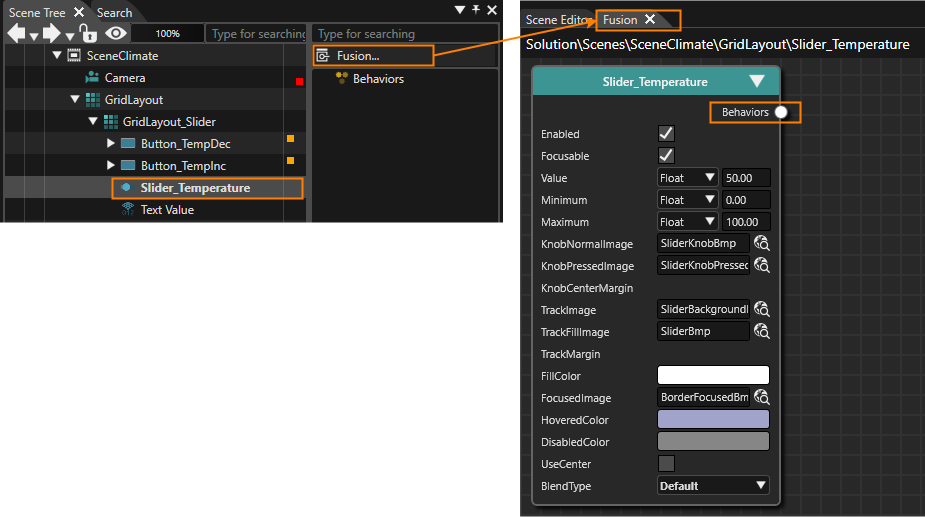
In the Scene Tree panel select the Slider_Temperature and click on the [Fusion...] buttonicon on the right side of the
Scene Tree.
Fusion will be opened, hiding the Scene Editor.
The Fusion diagram displays the Slider_Temperature's Fusion node.
In Fusion drag the Slider_Temperature node's Behaviors connector to the right and then release the mouse button.
The Select Behaviors dialog will be opened, which displays a list of behaviors. The behaviors in this list are organized in categories similar to the list of behaviorsproperty in the
ToolboxProperties panel's [Behaviors] section.
Directly above the list of behaviors is an input field.
Click into the input field above the behaviors listpanel and
start typing "Forward Value".
While typing the list of behaviors will be narrowed down, so that you can easily find the Forward Value behavior.
As soon as you can find the "Forward Value" behavior, double-click it.
A [Forward Value] node will be added to the Fusion diagram.
In the [ForwardValue] Fusion node click on the magnifying glass icon next to the property "TargetNode".
The Choose Item dialog will be opened.
Select the TargetNode as in the table below and click [OK].
The [Forward Value] Fusion node's TargetNode is configured.
TargetNode
Path
/Scenes/SceneClimate/GridLayout/GridLayout_Slider/Text Value
Switch back to the Scene Editor and press the <F5> key to trigger a refresh.
In the Scene Editor you can see thatselect the Text Value
willControl displayfrom "22°C",the whichchoose item dialog.
And this is what the value currentlyfully configured Slider looks like.
Our next goal is to center all cell content vertically in order to have a similar distance between the Sliderlines. control.Even
for multiple lines inside a Beautifyingcell Temperaturethe Settingoptical Controls
impression will be improved
TheWe defaulthave visualalready appearancecentered the text controls. Next, we will set VerticalAlignment of the Scenefollowing Composer's Slider does not fitcontrols to thisVCenter:
sample's
design.
Setting up the Slider's images are exchangeable, so are the Button's images.
In the Scene Tree panel select Button_TempDec. In the Properties panel press the magnifying glass icon next to the property "Normal Image" to open the "Choose Item" dialog.
The "Choose Item" dialog will be opened.
Select image "/Resources/Climate/NewTempDecreaseBmp" and press OK.
The "Choose Item" dialog will be closed.
Property "Normal Image" is set to "NewTempDecreasBmp".
In the Scene Editor a new image will be displayed differently.
Repeat steps 1 and 2 to set a new "Pressed Image" for Button_TempDec. Finally, Button_TempDec should be configured according to the table below.
Button_TempDec is configured with new "Normal Image" and "Pressed Image" which completely changed its appearance.
Target Item
Property
Image
Button_TempDec
Normal Image
/Resources/Climate/NewTempDecreaseBmp
Pressed Image
/Resources/Climate/NewTempDecrease_pressedBmp
In the Scene Tree panel select Button_TempInc and repeat steps 1 to 3 above to configure new images for "Button_TempInc" according to the table below.
Button_TempInc is configured with new "Normal Image" and "Pressed Image" changing its appearance completely.
Target Item
Property
Image
Button_TempInc
Normal Image
/Resources/Climate/NewTempIncreaseBmp
Pressed Image
/Resources/Climate/NewTempIncreae_pressedBmp
In the Scene Tree panel select "Slider_Temperature". In the [ Control ] section of the Properties panel set new images according to the table below.
In the Properties panel the Slider Control's image properties are configured with new images.
In the Scene Editor you can see the final result of the configured Temperature Slider Control.
Property
Image
Knob Normal Image
/Resources/Climate/NewSliderKnobBmp
Knob Pressed Image
/Resources/Climate/NewSliderKnobPressedBmp
Track Image
/Resources/Climate/NewSliderBackgroundBmp
Track Fill Image
/Resources/Climate/NewSliderBmp
Configuration of Steering Wheel Heating CheckBox
Controls
SteeringTo wheelconfigure the heating is easy to configure. It uses a simple CheckBox Control for turning the steering wheel heating on and off.
From the Toolbox panel's [ Controls ] section under "Touchable" drag and drop a "CheckBox" into the Scene Tree panel directly onto the already configured "GridLayout" node.
The CheckBox will appear in the Scene Tree panel.
The CheckBox will also be visible in the Scene Editor.
In the Scene Tree panelcontrols, select
the CheckBox and rename it to "CheckBox_Steering heater" either via the context menu entry "Rename" or by pressing <F2> on your keyboard.
In the Scene Tree panel, the "CheckBox_Steering heater"
can be seen.
In the Scene Tree panel right-click on the "GridLayout". In the opened context menu choose "Configure Layouter...".
The Grid Layout Editor will be opened.
The newly added CheckBox will be placed in the grid's top left cell.
In the Grid Layout Editor drag and
drop the CheckBox into the cell to the right of "Text_Steering wheel heating". When you're done, press [OK].
The Grid Layout Editor will be closed.
In Scene Editor the CheckBox will be positioned in the correct cell of the GridLayout.
In the Properties panel's [ Layout ] section change
the "Vertical Alignment" to VCenter.
In the Scene Editor the CheckBox's position has changed, it is now in the same line as theits text
"Steering wheel heating".
In the Properties panel's [ Control ] section change the Text to "On"
and.Finally, configure
the CheckBox's images as in the table below.
In the Scene Editor the CheckBox has a different visual appearance with the new images.
The Steering Wheel heating Controls have been configured correctly.
Property
Image
Normal Image
/Resources/Climate/NewCheckBoxDeselectedBmp
Pressed Image
/Resources/Climate/NewCheckBoxDeselectedPressedBmp
Selected Image
/Resources/Climate/NewCheckBoxSelectedBmp
Selected Pressed Image
/Resources/Climate/NewCheckBoxSelectedPressedBmp
Configuration of Air Conditioning RadioButtons
This scene uses RadioButtons to configure Air Conditioning values. RadioButtons need to be put into a common GroupBox in order to ensure their functionality.
Since these RadioButtons should fit into the scene's design, we will exchange the images for various"CheckBox_Steering statesheater" as below:
The configured "Checkbox_Steering heater" now looks like normal,this.
pressed,
Setting up the Air Condition Controls
In this section we focus on the Radioradio Buttonsbuttons for Air Condition (AC). TwoThe Text of the Radio Buttons areneeds configuredto insidebe achanged horizontalto Stack"Off" Layout.and They are grouped together"On" in arespect GroupBox to helptheir withnames. "RadioButton_AC Off" should be the RadioButtons'one functionality.
Fromon the
Toolboxleft, panel'sso [you Controlsmight ]have sectionto underchange "Container"the dragorder andof dropthe aRadioButtons "GroupBox" intoin the Scene Tree
panelPanel.Additionally, directlywe onto the configured "GridLayout" node.
In the Scene Tree panel the GroupBox is visible, hierarchically below the GridLayout.
In the Scene Tree panel click the triangle on the left of the GroupBoxhave to
open the GroupBox.
"Content" gets visible below "GroupBox".
From the Toolbox panel's [ Nodes 2D ] section drag and drop a "Stack Layout" into the Scene Tree panel directly onto the "Content" anchor of the GroupBox that has been added in the first step.
In the Scene Tree panel the Stack Layout has been added as the GroupBox's content.
From the Toolbox panel's [ Controls ] section under "Touchable" drag and drop 2 "Radio Buttons" into the Scene Tree panel directly onto the "Stack Layout" that has been added in the previous step.
In the Scene Tree panel the RadioButtons have been added to the Stack Layout.
In the Scene Tree panel select the "GroupBox" and "RadioButtons" individually and rename them according to the table below either via the context menu entry "Rename" or by pressing <F2> on your keyboard.
In the Scene Tree panel, "RadioButton_AC On" and "RadioButton_AC Off" can be seen as in the image below.
Target Item
Name
GroupBox
GroupBox_AC
RadioButton
RadioButton_AC Off
RadioButton_1
RadioButton_AC On
In the Scene Tree panel right-click on the GridLayout and choose "Configure Layouter..." from the context menu.
The Grid Layout Editor will be opened.
In the Grid Layout Editor drag and drop GroupBox_AC onto its correct position to the right of "Text_Air Condition". When you're done press [OK].
In the Scene Editor you can see that GroupBox (and its RadioButton content) is inconfigure the correct
cell in the GridLayout's grid.
In the Scene Tree panel select the Stack Layout. In the Properties panel's [ Layout ] section set the Vertical Alignment property to "VCenter".
In Scene Editor the Radio Buttons appear in correctly aligned with the text "Air Condition".
In the Scene Tree panel select GroupBox_AC. In the Properties panel's [ Control ] section uncheck the "Enable Background" property.
In Scene Editor you can see that a border around the Radio Buttons disappears.
To adjust the Radio Buttons to the general look and feel of the scene we will configure new images for them.
our Remember:RadioButtons. IfRemember if you select both RadioButtons in a "multiple selection" in the Scene Tree panel, you can configure the propertiesimages that are the same forof both RadioButtons at once.
In the Scene Tree panel select the Radio Buttons individually. In the Property panel's [ Control ] section change the "Text" property according to the table below.
In the Scene Editor the Radio Buttons' texts appear as configured.
Target Item
Text
RadioButton_AC On
On
RadioButton_AC Off
Off
In the Scene Tree panel select both Radio Buttons. This can be achieved by selecting one Radio Button and click on the second Radio Button while keeping the <Shift> key pressed.
In the Scene Tree panel and in the Scene Editor you can see that both Radio Buttons are selected.
In the Properties panel it says "Multiple items selected".
In the Properties panel's [ Control ] section define new images according to the table below. To do this, click the magnifying glass icon next to the image property to open the "Choose Item" dialog, where you select the corresponding image.
New images of the Radio Buttons have been configured.
Property
Image
Normal Image
/Resources/Climate/NewRadioButtonNormalBmp
Pressed Image
/Resources/Climate/NewRadioButtonNormalPressedBmp
Selected Image
/Resources/Climate/NewRadioButtonActivatedBmp
Selected Pressed Image
/Resources/Climate/NewRadioButtonActivatedPressedBmp
In the Properties panel's [ Layout ] section configure the Margin property of both Radio Buttons according to the table below.
In Scene Editor the two Radio Buttons are further apart than before.
The configuration of the Air Condition Radio Buttons and GroupBox is now complete.
Margin
Value
Left
0
Top
0
Right
100
Bottom
0

Keeping both RadioButtons selected, we will adjust the right margin to 100 so that there is enough space between them.
The default background of FanGroupBoxes Controlsmakes
Inthem appear with a frame. As we don't want to see a frame in our scenariodesign, we have to uncheck the "Enable Background" property of the GroupBox.
The height of our GroupBox_AC should be set to 40.
Currently the GroupBox height is calculated automatically based on the layout situation. Properties that are calculated automatically are displayed grayed out, the text "(Auto)" is displayed next to the value ofand the fanyou can be controlled by two Buttons and a MultiStateButton. These Controls are arranged by a GridLayout.
The MultiStateButton is configured to have 8 different states, for which 8 different images are provided.
The Buttons' images are updated as well, matching to the scene's design and their functionality.
Interactivity between each Button and the MultiStateButton is provided by an EventHandler. A SendValueByEvent behavior will send a configured value to the TargetNode "MultiStateButton" wheneversee a button with an "A" on it next to it.
In order to be able to enter a value manually, you have disable the automatic calculation by pressing the blue "A" button first.
You can see the tooltip for the blue "A" button in the image below.
You might have wondered why we added a StackLayout previously. The reason is, the Stack Layout is clicked.able to layout child nodes horizontally or vertically. The "horizontal" arrangement is the one we need.
Setting up the Fan Controls
Now
we take
care Fromof the
ToolBoxGridLayout_Fan. panel'sOpen [the Nodes"Configure 2DLayouter…" ] section dragdialog and
dropconfigure athe GridLayout
intoas the Scene Tree panel directly onto the already existing "GridLayout" node.
In the Scene Tree panel you can see that a GridLayout has been created under the already existing GridLayout. The newly created GridLayout is hierarchically below the older GridLayout.
From the ToolBox panel's [ Controls ] section under "Touchable" drag and drop 2 Buttons and 1 MultiStateButton into the Scene Tree panel directly onto the node "GridLayout" that was createdshown in the
previous step.picture.
In the Scene Tree panel you can see that 2 Buttons and 1 MultiStateButton have been created below the GridLayout that has been created in the previous step.
In the Scene Tree panel create a multiple selection of all Fan Controls (GridLayout, the 2 Buttons and MultiStateButton) by clicking on the first one, holding the <Shift>-key on your keyboard and then clicking on the last one.
In the Scene Tree panel 4 items are selected.
In the Properties panel's top it says "Multiple items selected".
In the Properties panel's [ Layout ] section change the VerticalAlignment to VCenter.
Vertical Alignment of all 4 nodes is set to center.
In the Scene Tree panel select the newly created GridLayout, Buttons and MultiStateButton individually and rename them according to the table below either via the context menu entry "Rename" or by pressing <F2> on your keyboard.
In the Scene Tree panel the newly created Controls appear as in the image below.
Target Item
Name
GridLayout
GridLayout_Fan
Button
Button_Fan Off
Button_1
Button_Fan Max
MultiStateButton
MultiStateButton_Fan
In the Scene Tree panel right-click on the "older" GridLayout and choose "Configure Layouter..." from the context menu.
The "Grid Layout Editor" will be opened.
In the "Grid Layout Editor" drag and drop GridLayout_Fan into the cell right next to the "Text_Fan" Text control. Then click [OK].
In Scene Editor GridLayout_Fan and its content is now placed at the correct position.
The MultiStateButton and the 2 Buttons are still overlapping. This will be solved by configuring the layout of GridLayout_Fan in the next steps.
Configuring GridLayout_Fan
In the Scene Tree panel right-click on the GridLayout_Fan and choose "Configure Layouter..." from the context menu.
The "Grid Layout Editor" will be opened.
In the "Grid Layout Editor" configure 1 row and 6 columns using the buttons on the bottom left.
In the "Grid Layout Editor" a grid with rows and columns will be displayed as configured.
In the "Grid Layout Editor" adjustFor the width of the
columnsthird oncolumn, we are using the
topexact width of the
grid.MultiStateButton's Thenimage dragin andorder dropto get a pixel exact rendering of the
controlsimage.
We now configure the images of the MultiStateButton. You can find a property "StateImages" in the Control section of the MultiStateButton's properties, where multiple images can be defined.
It is possible to theiradd destinationimages positionusing asthe seen"+" button or to remove images using the "x" button next to the image to be deleted (highlighted in the image below and click [OK]above).
The "Grid Layout Editor" is configured as in the image.
After pressing [OK], the controls of GridLayout_Fan are arranged as in the image below.
Configuring MultiStateButton_Fan
In the Scene Tree panel select MultiStateButton_Fan. In the Properties panel's [ Layout ] section set the Vertical Alignment to VCenter.
In the Properties panel's [ Control ] section set "Maximum State" to the value of "7".
In the properties panel the Maximum State property is set to 7.
In the Properties panel's [ Control ] section click on the "StateImages" property.
In the Properties panel the StateImage property will be expanded.
Press the [ + ] button on the right of the "StateImages" property until there are 8 StateImages in the list below.
In the Properties panel the list of StateImages will consist of entries from "StateImages 0" to "StateImages 7".
In the Properties panelPlease click on the magnifying glass
next to
"StateImages 0".
The "Choose Item" dialog will be opened.
Inchange the
Chooseimages. ItemFor dialogour navigateGettingStarted, to "/Resources/Climate/NewClimate-0Bmp", select this image and click [OK].
In the Properties panel the first StateImage has been configured.
Repeat steps 4 and 5 to configure the remaining StateImages as in the table below.
In Properties panel all StateImages are configured.
In Scene Editor you can see the newly configured images.
If the new images are not visible try refreshing the screen by pressing the <F5> key on your keyboard.
StateImages
Image Path
StateImages 0
/Resources/Climate/NewClimate-0Bmp
StateImages 1
/Resources/Climate/NewClimate-1Bmp
StateImages 2
/Resources/Climate/NewClimate-2Bmp
StateImages 3
/Resources/Climate/NewClimate-3Bmp
StateImages 4
/Resources/Climate/NewClimate-4Bmp
StateImages 5
/Resources/Climate/NewClimate-5Bmp
StateImages 6
/Resources/Climate/NewClimate-6Bmp
StateImages 7
/Resources/Climate/NewClimate-7Bmp
Configuring Fan Buttons
In the Scene Tree panel select "Button_Fan Off". In the Properties panel's [ Control ] section click the magnifying glass icon next to the "Normal Image" property.
The "Choose Item" dialogwe will
be opened.
In the Choose Item dialog select "/Resources/Climate/NewButton offBmp" and click [OK].
A new image is configured for "Button_Fan Off".
In the Scene Editor the new image for the button is displayed.
Repeat steps 1 and 2 above to configure the images
forfrom the climate folder of our resources ("NewClimate-0Bmp" - "
Button_FanNewClimate-7Bmp"). Off"We and "Button_Fan Max" accordinghave to
the table below
The images forchange the
FanMaximum ButtonsState have been changed.
In Scene Editor the new normal images can are visible.
Target Item
Property
Image Path
Button_Fan Off
Normal Image
/Resources/Climate/NewButton offBmp
Pressed Image
/Resources/Climate/NewButton offselectedBmp
Button_Fan Max
Normal Image
/Resources/Climate/NewButton maxBmp
Pressed Image
/Resources/Climate/NewButton max_selectedBmp
Add Interactivityproperty to Fan7 Controls
in order to be able to display all selected images.
The MultiStateButton should be centered vertically, so we configure its layout accordingly.
To change the image of "Button_Fan Max" and "Button_Fan Off" use the resources available. A button needs two different images to be able to reflect a mouse press or a touch on a touch screen. Therefore we will change the normal and pressed image as shown below:
Both buttons should be centered vertically. Therefore we will select both buttons and set the vertical alignment to "VCenter".
panel
Improvement of Interactivity using Behaviors
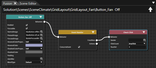
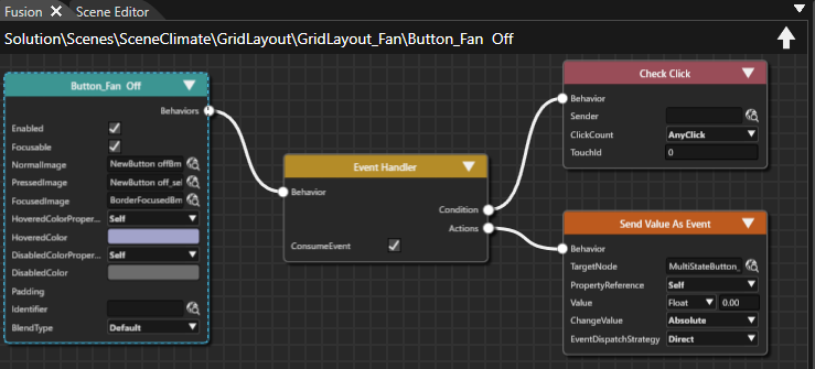
We want to add the reset of the MultiStateButton_Fan to the off button and also we want to add the max functionality to the max button. To be able to do this we will need to use an Event Handler. When you select the "Button_Fan Off" andyou clickcan onrecognize thetwo [Fusion...]tabs: buttonan onactive the"General" right side of the Scene Tree.
Fusion will be opened, displaying a Fusion diagram as shown in the image below.
Drag the Event Handler's Actions connector of the righttab and
releasean theEventHandler mouse button.
The Select Behavior dialog will be displayed.
Position the mouse cursor into the input field above the behaviors list and start typing "Send Value as Event". As soon as you find the behavior in the list, which is narrowed down while typing, double-click it.
A new Fusion node [Send Value as Event] is added to the Fusion diagram.
Configure the [Send Value as Event] behavior's TargetNode by pressing the magnifying glass icon next to it. In the opened Select Item dialog navigate to the MultiStateButton_Fan, which can be found at the path given in the table below. Select MultiStateButton_Fan and press [OK].
MultiStateButton_Fan is configured as TargetNode, where the value will be sent to when a click action occurs on "Button_Fan Off".
Configure the Fusion node's value according to the table below.
[Button_Fan Off] is configured to send a value of 0.00 to MultiStateButton_Fan whenever it is pressed.
Button_Fan Off
Fusion Node: Send Value As Event
TargetNode
/Scenes/SceneClimate/GridLayout/GridLayout_Fan/MultiStateButton_Fan
Value
Float 0.00
Repeat steps 1 to 5 with "Button_Fan Max" setting the Action's value to the maximum fan value of "7".
[Button_Fan Max] is configured to send a value of 7.00 to MultiStateButton_Fan whenever it is pressed.
Button_Fan Off
Fusion Node: Send Value As Event
TargetNode
/Scenes/SceneClimate/GridLayout/GridLayout_Fan/MultiStateButton_Fan
Value
Float 7.00
tab:
Select this "Event Handler" tab to be able to attach functionality to the button. Use the "+" button net to "Actions" to add an action to the already attached "Click Event Handler".
Configuration of Seat Heater MultiStateButton
From the ToolBox panel's [ Controls ] section under "Touchable" drag and drop 1 MultiStateButton into the Scene Tree panel directly onto the scene's GridLayout.
In the Scene Tree panel you can see that a MultiStateButton has been created below the scene's GridLayout that has been created in one of our first steps on this page.
In the Scene Tree panel select the MultiStateButton and rename it to "MultiStateButton_Seat" either via the context menu entry "Rename" or by pressing <F2> on your keyboard.
In the Scene Tree panel, the "MultiStateButton_Seat" can be seen.
In the Scene Tree panel select MultiStateButton_Seat. In the Properties panel's [ Layout ] section change the VerticalAlignment to VCenter.
In the Scene Editor MultiStateButton_Seat is displayed vertically centered inside its cell.
In the Scene Tree panel right-click on the scene's GridLayout and choose "Configure Layouter..." from the context menu.
The "Grid Layout Editor" will be opened.
In the "Grid Layout Editor" drag and drop MultiStateButton_Seat into the cell right next to the "Text_Seat heater" Text control. Then click [OK].
In Scene Editor MultiStateButton_Seat is now placed at the correct position.
In the Scene Tree panel select MultiStateButton_Seat. In the Properties panel's [ Control ] section under "StateImages" click on the magnifying glass next to "StateImages 0".
The "Choose Item" dialog will be opened.
In the Choose Item dialog navigate to "/Resources/Climate/NewButtonState1Bmp", select this image and click [OK].
In the Properties panel the first StateImage has been configured.
Repeat steps 6 and 7 to configure the remaining StateImages as in the table below.
In Properties panel all StateImages are configured.
In Scene Editor you can see the newly configured images.
If the new images are not visible try refreshing the screen by pressing the <F5> key on your keyboard.
StateImages
Image Path
StateImages 0
/Resources/Climate/NewButtonState1Bmp
StateImages 1
/Resources/Climate/NewButtonState2Bmp
StateImages 2
/Resources/Climate/NewButtonState3Bmp
StateImages 3
/Resources/Climate/NewButtonState4Bmp
You can check the functionality by changing the Control's "Current State" property to any value from 0 to 3 in the Properties panel's [ Control ] section.
In the Scene Editor a different image will be displayed for the Seat heater depending on the configured value of the "Current State" property.
Below you can see the MultiStateButton_Seat when "Current State" is 3.

Use the drop down menu to choose "Send Value As Event". Select the "MultiStateButton_Fan" as TargetNode using the magnifying glass.
Configuration
The Event Handler tab should now look like this:
Due to the more complex possibilities of Heatingevent SpinBoxhandlers we will now explain in more detail what the different properties are usually used for.
With
the Event drop down you can select on which type of event a certain action will be performed. In our case a click event(mouse click or touch) will trigger the action. For a description of available events please have a look inside the documentation FeatStd::Event. The Condition property can be used for some events to only react if a certain condition is evaluates to "true". For our case the "Check Click" will count the number of clicks happened and compares it with the given ClickCount property. We have provided AnyClick which means we will react on single, double and even triple clicks. With the Sender property we can give the Action Behavior additional information on who has executed the action. In our example we do not evaluate this sectionand it is left empty.
The Value is used to specify the type of the value and the value itself which will be sent to the target node. ChangeValue states if the change of the value will be relative or absolute.
Last but not least the Target Node has to be specified to know who will be the receiver of the event.
We will now add a similar action to the "Button_Fan Max" button to always change the value of the MultiState button to its maximum value of 7.
Setting up the Seat Heater controls
For the Seat Heater controls, we just need to replace the images with new ones, as below:
Setting up the Heating controls
Last but not the least, we will configure the Heating control.SpinBox. The SpinBox allows the user to change the values by clicking the uptick and downtick buttons.
We will configure the SpinBox control as follows. We will also change the images of the SpinBox Control.
From the Toolbox panel's [ Controls ] section under "Touchable" drag and drop a SpinBox into the Scene Tree directly onto the scene's GridLayout.
In the Scene Tree panel you can see that SpinBox has been created below the scene's GridLayout that has been created in one of our first steps on this page.
In the Scene Tree panel select the SpinBox and rename it to "SpinBox_Heating" either via the context menu entry "Rename" or by pressing <F2> on your keyboard.
In the Scene Tree panel, the "SpinBox_Heating" can be seen.
In the Scene Tree panel select SpinBox_Heating. In the Properties panel's [ Layout ] section change the VerticalAlignment to VCenter and change the Size's X property to "150".
To change the Size's X property you might have to click the disabled [ A ] button first.
In the Scene Editor SpinBox_Heating is displayed vertically centered inside its cell and its width is reduced to 150px.
Target Item
Value
Vertical Alignment
VCenter
Size X
150,00
In the Scene Tree panel right-click on the scene's GridLayout and choose "Configure Layouter..." from the context menu.
The "Grid Layout Editor" will be opened.
In the "Grid Layout Editor" drag and drop SpinBox_Heating into the cell right next to the "Text_Heating" Text control. Then click [OK].
In Scene Editor SpinBox_Heating is now placed at the correct position.
In the Scene Tree panel select Spinbox_Heating. In the Properties panel's [ Control ] section adjust the properties given in table below.
SpinBox_Heating is configured according to the table.
In Scene Editor the displayed text is changed to "22°C".
If the displayed value doesn't change to "22°C" try refreshing the screen by pressing the <F5> key on your keyboard
Target Item
Value
Value
Float 22.00
Minimum Value
Float 15,00
Maximum Value
Float 28,00
Text Format
%02d°C
In the Properties panel's [ Control ] section click on the magnifying glass icon next to "Arrow Up Normal Image".
The "Choose Item" dialog will be opened.
In the Choose Item dialog select /Resources/Climate/New_arrow_incrementBmp
In Scene Editor you can see that a new image has been configured for the SpinBox.
Repeat steps 7 and 8 to configure new images according to the table below.
In Properties panel new images are configured for the SpinBox_Heating as seen in the image below.
In the Scene Editor new images are visible for the SpinBox.
Target Item
Value
Arrow Up Normal Image
/Resources/Climate/New_arrow_incrementBmp
Arrow Up Pressed Image
/Resources/Climate/New_arrow_increment_activeBmp
Arrow Down Normal Image
/Resources/Climate/New_arrow_decrementBmp
Arrow Down Pressed Image
/Resources/Climate/New_arrow_decrement_activeBmp

CheckSet the Climateheight Scene
of the SpinBox to 150. Please note that this is an automatically calculated property which has to be unlocked pressing the blue "A" button.
The Climate scene is now finished.
To
check
You have finished step 2 of our tutorial. Please save your solution before trying the result of configuringusing the firstPlayer scene,application. openGenerate an asset file as described at the displayend view.of ThisStep view1. representsLoad the finalgenerated renderedasset resultinto the Player and can be opened viaselect the menu:climate Viewscene. - Display - Display-0.
The display panel will be opened in a floating way displaying the scene configured in the steps above.
In the Scene Composer's Toolbar make sure that the item "Generate and Play" is selected in the drop-down menu and click the [ > ] button to the left.
This will generate the asset so it is available as input for the Player. After that the CGI Panel will be started.
In the CGI Panel tick the checkbox next to "Scenes#SceneClimate" and uncheck "Scenes#SceneHome".
SceneClimate will become visible in the Player.
You can now play around with the
configuredcontrols. Climate Controls inSlide the
scenetemperature slider, use the check box and
watchradio buttons. Click onto the
results.fan multi Temperaturestate slider is workingbutton and
theon displayed temperature is updated.
Steering wheel heating CheckBox can be checkedoff and
uncheckedmax. AirEven Conditioningthe RadioButtons can be toggled
Fan Buttons and MultiStateButton can be clicked and are functional.
Seat heater
MultiStateButton can be clicked and will
changereact itson imageyour Heatingactions.
SpinBox
can be configured for values from 15 to 28°C