Advanced Cluster Part 4
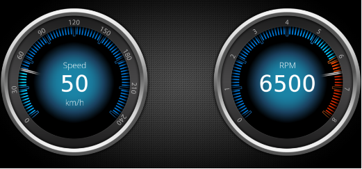
The following steps describe how to use the Custom_Gauge control in a scene. Speed gauge and RPM gauge are realized with the same control. Using the public properties for customization these Gauge controls appear similar yet different.
Once the advanced cluster scene is fully configured, it's time to test its functionality using the Scene Composer's Player.
Create a Cluster Scene with 2 Custom_Gauge Controls
- In the Solution Explorer navigate to the Scene2D and double click it.
- Scene2D will be opened and visible in Scene Editor and Scene Tree panel.
- In Scene Tree panel you can see that the scene contains a camera.
- In the Scene Editor's bottom toolbar make sure that "active rendering" and "widgets updating" is enabled.
- In the Scene Editor's bottom toolbar "active rendering" and "widgets updating" are highlighted as seen in the image below.

- In the Scene Editor's bottom toolbar "active rendering" and "widgets updating" are highlighted as seen in the image below.
- From the Toolbox panel under [Nodes 2D] drag a Group node into the Scene Tree panel or the Scene Editor.
- In the Scene Tree panel you can see the newly created Group node.
- In the Scene Editor you can see an indicator of the Group node's current position.
- In the Scene Tree panel you can see the newly created Group node.
- Rename the Group node according to the table below either via the context menu "Rename" or the keyboard shortcut <F2>.
- The Group node has been renamed accordingly.
Old Name New Name Group Group_Content
- The Group node has been renamed accordingly.
- In the Scene Tree panel select the Group node. In the Properties panel's [Transformations] section reset the Position property according to the table below.
- In the Scene Editor you can see the Group node's current position.
A property can easily be reset in the Properties panel by clicking on the curled arrow icon on the property's left.
Target Item Position X Y Group_Content 0.00 0.00
- In the Scene Editor you can see the Group node's current position.
- From the Solution Explorer drag the image according to the table below into the Scene Tree panel directly onto the Group_Content node.
- In Scene Tree panel you can see that a new RenderNode2D with a BitmapBrushBlend effect has been created inside Group_Content.
- In Scene Editor you can see the rendered background image.
Path in Solution Explorer Image Solution > Resources > Bitmaps BackgroundBmp
- From the Solution Explorer drag two Custom_Gauge into the Scene Tree panel directly onto the Group_Content. The path to the Custom_Gauge control is given in the table below.
- In the Scene Editor only one Custom_Gauge will be displayed since both controls are located at the same position and therefore are completely overlapping. One Custom_Gauge is hiding the other.
- In the Scene Tree panel the Group_Content node contains a RenderNode2D and the newly created Custom_Gauges.
Path in Solution Explorer Control Solution > Controls Custom_Gauge
- Rename the Custom_Gauge nodes according to the table below either via the context menu "Rename" or the keyboard shortcut <F2>.
- The Custom_Gauge node has been renamed accordingly.
Old Name New Name Custom_Gauge Custom_Gauge_Speed Custom_Gauge_1 Custom_Gauge_RPM
- The Custom_Gauge node has been renamed accordingly.
- Select the Custom_Gauge controls one after the other. In the Properties panel configure the properties as given in the
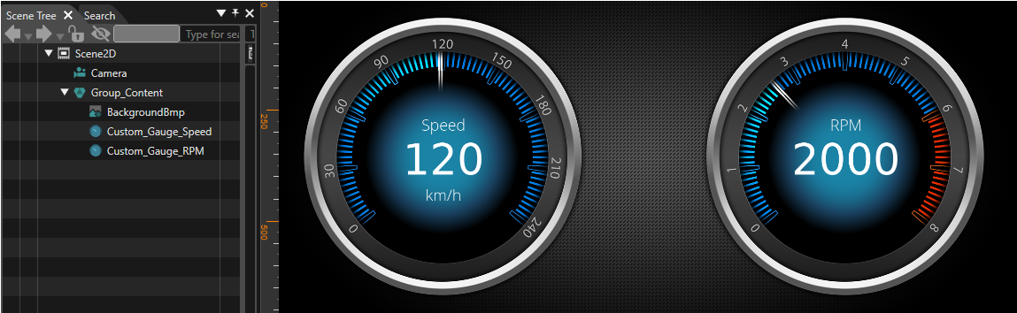
tabletables below.- In the Scene Editor the gauge controls for RPM and Speed are both
visiblevisible.
and - In the Scene Editor the gauge controls for RPM and Speed are both
- The
configuredScene2D starts tobelookdistinguishable.like a cluster, see image below.
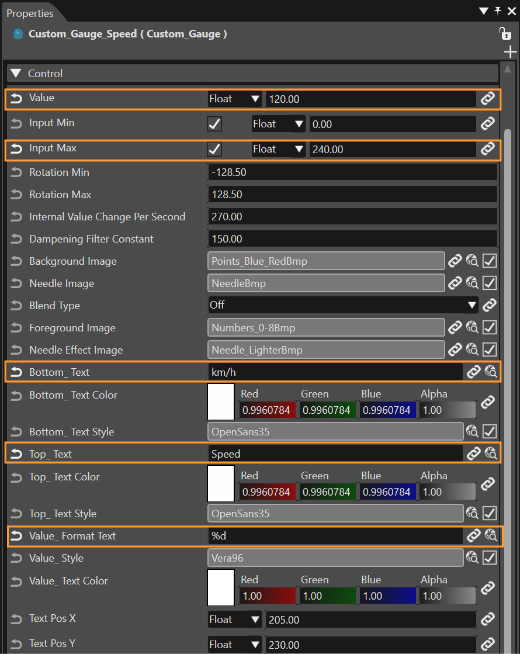
Position X 965.00 Position Y 30.00Custom_Gauge_RPM Property Value Transformation Custom_Gauge_Speed Property Value Transformation Position X 60.00 Position Y 30.00 Control Value 120 Input Max 240 Top_Text Speed Value_Format Text %d Bottom_Text km/h BackgroundImage Solution/Resources/Bitmaps/Points_BlueBmp ForegroundImage Solution/Resources/Bitmaps/Numbers_0-240Bmp
Check the Scene in the Player
• Insert the “BackgroundBmp” (Solution->Resources->Bitmaps) to the group
• Place a Custom_Gauge into the group, name it as “Custom_Gauge_Speed”
• Set the position: X = 60, Y = 30
• Clone the “Custom_Gauge_Speed”, name it as “Custom_Gauge_RPM” and set its X position: X = 965
• Select the “Custom_Gauge_Speed” and go to its properties. Set these settings:Input Max = 240, Value = 120, Top_Text = Speed, Value_Format Text = %d, Bottom_Text = km/h
• Set the BackgroundImage to “Points_BlueBmp”
• Set the ForegroundImage to “Numbers_0-240Bmp”
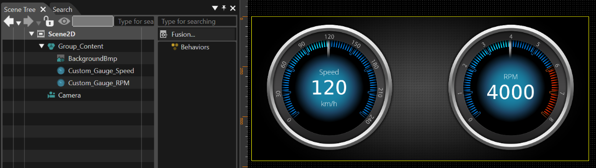
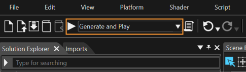
• The scene is ready. Now you can try to run it in the Player by selecting "Generate and Play" and pressing the play button in the top panel
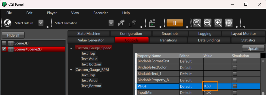
• When the Player appears, you can manually change the accessible values for selected controls:
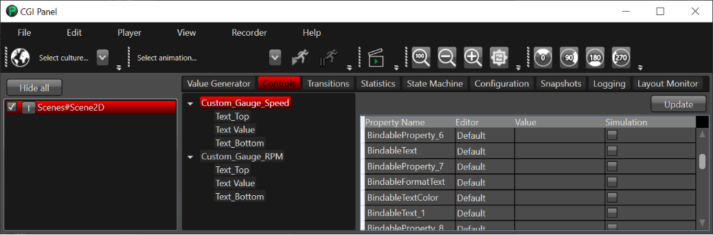
• The changes should be immediately reflected on the display: