# View Editor

# Overview

**View Editor** is the feature set in SceneComposer for designing and managing <span style="color:rgb(230,126,35);">[**View**](https://doc316en.candera.eu/books/view-editor/page/view)</span>s. You can compose screen-level Views by combining Scenes and existing Views, structure their transitions as a tree, and export the result as a Global State Machine asset. In addition, you can visually define event logic and screen transitions for each View as <span style="color:rgb(230,126,35);">[**Action Chains**](https://doc316en.candera.eu/books/view-editor/page/action-chain-editor)</span> and reuse them as conditional processing based on input devices and the solution state by using the **ConditionOutputs** defined in ConditionBlocks created in the <span style="color:rgb(230,126,35);">[**Condition Editor**](https://doc316en.candera.eu/books/view-editor/page/condition-editor)</span>.

This page provides the View Editor feature set used to work with them. The View Editor consists of the following four panels.

<p class="callout info">For details on Views, see the <span style="color:rgb(230,126,35);">[View overview page](https://doc316en.candera.eu/books/view-editor/page/view)</span>.</p>

<table id="bkmrk-view-definition-edit" style="border-collapse:collapse;width:100%;height:257.835px;"><colgroup><col style="width:24.2208%;"></col><col style="width:75.8875%;"></col></colgroup><tbody><tr style="height:80.1136px;"><td style="height:80.1136px;"><span style="color:rgb(230,126,35);">[View Definition Editor](https://doc316en.candera.eu/books/view-editor/page/view-definition-editor)</span></td><td style="height:80.1136px;">An editor for defining screen-level Views by combining Scenes and existing Views, and for managing screen composition information. Views defined here are referenced as the common screen unit from the **View Tree**, the state machine, and the **Action Chain Editor**.

</td></tr><tr style="height:80.1136px;"><td style="height:80.1136px;"><span style="color:rgb(230,126,35);">[View Tree](https://doc316en.candera.eu/books/view-editor/page/view-tree)</span></td><td style="height:80.1136px;">An editor for arranging Views in the solution as a tree and designing screen transitions based on that structure. The structure you configure is exported as a Global State Machine and used as the candidate targets for the <span style="color:rgb(230,126,35);">[**JumpToView** Action behavior](https://doc316en.candera.eu/link/582#bkmrk-jump-to-view)</span> configured in the **Action Chain Editor**.

</td></tr><tr style="height:62.3097px;"><td style="height:62.3097px;"><span style="color:rgb(230,126,35);">[Action Chain Editor](https://doc316en.candera.eu/books/view-editor/page/action-chain-editor)</span></td><td style="height:62.3097px;">This editor lets you visually define event processing and screen transitions for a View as trigger-based flowcharts. For each View selected in the **View Tree**, you associate an Action Chain and use **ConditionOutputs** created in the **Condition Editor** as branch conditions.

</td></tr><tr style="height:35.2983px;"><td style="height:35.2983px;"><span style="color:rgb(230,126,35);">[Condition Editor](https://doc316en.candera.eu/books/view-editor/page/condition-editor)</span></td><td style="height:35.2983px;">The Condition Editor is an editor for visually defining conditions that are evaluated in Action Chains or assigned to the Condition properties of behaviors/Fusion as **ConditionOutputs** inside ConditionBlocks. The created ConditionOutputs can be reused as branch conditions in the Action Chain Editor and referenced from multiple locations in the solution as shared conditional logic.

</td></tr></tbody></table>

Used together, these let you define View-based screen composition and transition logic in a consistent, unified way.

# View

**View** sits above Scene in the hierarchy: you can treat a single Scene as one screen, or group multiple Scenes and/or existing Views into a single screen state. Each View is a logical unit that specifies what content to display and how to display it on a given screen. On the engine side, Views are identified by the dedicated identifier type `ViewIdentifier`.

A View is authored primarily in the [**View Definition Editor**](https://doc316en.candera.eu/books/view-editor/page/view-definition-editor), and the result is referenced as a common screen-level object from the [**View Tree**](https://doc316en.candera.eu/books/view-editor/page/view-tree), the <span style="color:rgb(230,126,35);">**[State Machine](https://doc316en.candera.eu/books/state-machine)**</span>, and the **[Action Chain Editor](https://doc316en.candera.eu/books/view-editor/page/action-chain-editor)**. Screen showing and hiding is handled automatically as part of internal processing, so users do not need to configure display-control elements directly. In the View Tree, you define the transition structure between multiple Views as a tree, and this information is exported as a **Global State Machine** asset. Furthermore, by combining the **Action Chain Editor** and the [**Condition Editor**](https://doc316en.candera.eu/books/view-editor/page/condition-editor), you can design view-level screen transitions and event logic that respond to input devices and the solution state.

By introducing Views, you can keep Scene-level layout definitions separate from screen-level transition/control logic, while organizing and maintaining the solution’s overall screen composition consistently at the View level.

#### Create a View (from a Scene)

When you create a View starting from a Scene, that Scene is automatically associated with the newly created View. You can use it immediately as the View that displays that Scene.

1. In **Solution Explorer**, select any **Scene**, then choose **Create View…** from the context menu.
    
    
    - The **Add** **New View** dialog opens.
2. Configure the required settings and click **OK**.
    
    
    - The value set in **Name** is used as the View’s display name in **Solution Explorer**.
    - The same value is also assigned automatically as the **View Identifier**.
3. A new **View** is created in **Solution Explorer** with the selected **Scene** as its child.

This operation automatically establishes the association between the View and the Scene.

#### Create a View (New Item)

If you create an empty View, you must later add and associate Scenes in the [**View Definition Editor**](https://doc316en.candera.eu/books/view-editor/page/view-definition-editor). This method lets you flexibly build composite Views that combine multiple Scenes.

1. In **Solution Explorer**, open the context menu at the desired location and choose **Add &gt; New Item**.
    
    
    - The **Add** **New View** dialog opens.
2. From the left menu, select **View**.
    
    
    - The View settings appear on the right.
3. Configure the required settings and click **OK**.
    
    
    - The value set in **Name** is used as the View’s display name in **Solution Explorer**.
    - The same value is also assigned automatically as the **View Identifier**.
4. A new **View** is created in **Solution Explorer**.

Because a View created by this method has no Scene associated yet, you need to add the Scene(s) you want to display later in the [**View Definition Editor**](https://doc316en.candera.eu/books/view-editor/page/view-definition-editor).

# View Definition Editor

**View Definition Editor** lets you define “screen-level Views” by combining Scenes created in SceneComposer with existing [**<span style="color:rgb(230,126,35);">Views</span>**](https://doc316en.candera.eu/books/view-editor/page/view), and make those definitions available to the **<span style="color:rgb(230,126,35);">[View Tree](https://doc316en.candera.eu/books/view-editor/page/view-tree)</span>**, the **State Machine**, and the <span style="color:rgb(230,126,35);">[**Action Chain Editor**](https://doc316en.candera.eu/books/view-editor/page/action-chain-editor)</span>.

Only **Views** are displayed as nodes in the tree of the **View Definition Editor** panel. Therefore, if you want to use a **Scene**, you must always include it as a component of one of the **Views**. For details, see <span style="color:rgb(230,126,35);">[**View composition**](#bkmrk-view-composition)</span> later in this document. With this structure, the state machine can consistently treat “which screen (View) to activate” at the View level, while still incorporating Scene-based content into the screen composition.

### View Definition Editor UI 

#### Panel layout

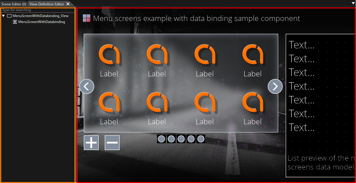
Double-click any **View** in **Solution Explorer** to open the **View Definition Editor** panel.

<div drawio-diagram="8825"><img src="https://doc316en.candera.eu/uploads/images/drawio/2025-12/drawing-4-1764895545.png" alt="drawing-4-1764895545.png"/></div>

<table id="bkmrk-ui-item-description-" style="width:800px;height:198.92px;border-collapse:collapse;"><thead><tr style="height:29.7017px;"><th style="width:276.009px;background-color:rgb(35,111,161);">**<span style="color:rgb(255,255,255);">UI item</span>**</th><th style="width:523.082px;background-color:rgb(35,111,161);">**<span style="color:rgb(255,255,255);">Description</span>**</th></tr></thead><tbody><tr style="height:46.5057px;"><td style="width:276.009px;height:46.5057px;">**View Composition pane** (orange frame in the figure above)

</td><td style="width:523.082px;height:46.5057px;">Lists which **Scenes/Views** the selected **View** is composed of. Add or remove Scenes and existing Views by **drag and drop**.

</td></tr><tr style="height:46.5057px;"><td style="width:276.009px;height:46.5057px;">**Preview area** (red frame in the figure above)

</td><td style="width:523.082px;height:46.5057px;">Displays preview images of the **Scenes/Views** associated with the View in the right pane, where you can also adjust their layout positions. Useful for improving visual identification when referencing this View from the **State Machine** or **View Tree**.

</td></tr></tbody></table>

<article class="text-token-text-primary w-full focus:outline-none [--shadow-height:45px] has-data-writing-block:pointer-events-none has-data-writing-block:-mt-(--shadow-height) has-data-writing-block:pt-(--shadow-height) [&:has([data-writing-block])>*]:pointer-events-auto scroll-mt-[calc(var(--header-height)+min(200px,max(70px,20svh)))]" dir="auto" id="bkmrk-basic-operations-thi" tabindex="-1">### Basic operations

This section outlines common procedures for defining and editing Views with the **View Definition Editor**.

<p class="callout info">For instructions on creating a **View**, see the <span style="color:rgb(230,126,35);">[View feature overview page](https://doc316en.candera.eu/books/view-editor/page/view)</span>.</p>

#### View composition

</article>In the **View Definition Editor** panel, you can use the tree structure to edit or delete child Views under the currently opened View. You can also review the entire tree rooted at that View on the tree, including the hierarchical relationships of its child Views and their descendant Views.

<p class="callout info">The composition editing described here applies to <span style="color:rgb(230,126,35);">[Views that were created as **new Views**](https://doc316en.candera.eu/link/1318#bkmrk-create-a-view-%28new-i)</span>. <span style="color:rgb(230,126,35);">[Views that were automatically generated from a Scene](https://doc316en.candera.eu/link/1318#bkmrk-create-a-view-%28from-)</span> are treated as simple Views that display the corresponding Scene, and you cannot edit the tree structure in the View Definition Editor or attach child Views or additional Scenes under them.</p>

1. Double-click the View in Solution Explorer whose composition you want to edit.  
    
    - The View Definition Editor panel opens and displays the composition of the selected View.
2. In the View Composition pane, edit the elements included in the View. 
    - If the target View does not yet have a Scene as a child element, you can add a Scene or an existing View by dragging and dropping it from Solution Explorer.
    - If the target View already has a *Scene* as a child element, you cannot add any additional Scenes or Views (a View that contains a Scene as a child is always treated as a leaf node).
    - To remove unnecessary elements (Scenes/Views), select them and choose **Delete** from the context menu.

##### Behavior when dragging and dropping a Scene

Only **Views** are shown as nodes in the tree of the View Definition Editor panel. If you want to work with a **Scene**, you add it as internal content of an existing View.

- When you drag and drop a Scene from Solution Explorer into the **Composition** pane of the View currently open in the View Definition Editor, the **Create View** dialog appears if there is no existing View that already has that Scene as its child.
- If you accept the creation in the dialog, a new View that contains the Scene as its child is automatically generated and added to the tree as a child View of the drop target View.

With this mechanism, the View Definition Editor tree can consistently treat the unit of screen transitions and visibility control as **Views**, while still allowing you to build Scene-based content within those Views.

##### Grandchild View

In the View Definition Editor panel, a single operation can add Views only up to **the child View directly under the currently open View** (one hierarchy level down). To create a structure with three or more hierarchy levels, such as **Parent View &gt; Child View &gt; Grandchild View**, you must use only Views that meet the following requirements as the starting point:

- The View you want to use as the parent level must be a <span style="color:rgb(230,126,35);">[**newly created View**](https://doc316en.candera.eu/link/1318#bkmrk-create-a-view-%28new-i)</span>.
- The View you want to use as the parent level must **not** already have a **Scene** as its child element.
- <span style="color:rgb(230,126,35);">[Views that were automatically generated from a](https://doc316en.candera.eu/link/1318#bkmrk-create-a-view-%28from-)</span><span style="color:rgb(230,126,35);">[ Scene](https://doc316en.candera.eu/link/1318#bkmrk-create-a-view-%28from-)</span>, or Views that already have a **Scene** as a child, **cannot** be used as the starting point for building a grandchild hierarchy (these Views are always treated as **leaf nodes**).

Using a View that meets these requirements as the starting point, create a three-level structure (**Parent View &gt; Child View &gt; Grandchild View**) as follows:

1. Open the View you want to use as the parent level, and add a child View under it (**Parent View &gt; Child View**).
2. Double-click the View you added as the child View in step 1 to open it, and then add another View under it as its child (**Child View &gt; Grandchild View**).

After performing these steps, reopen the original parent View. You can then confirm in the tree that a three-level hierarchy (**Parent View &gt; Child View &gt; Grandchild View**) is displayed.

# View Tree

**View Tree** is the editor for arranging <span style="color:rgb(230,126,35);">[**View**](https://doc316en.candera.eu/books/view-editor/page/view)</span> in the solution as a tree and composing screen transition logic based on that structure. When you define transition relationships between Views on the tree, that information is exported as the **Global State Machine** at asset generation and becomes available as destination candidates for the <span style="color:rgb(230,126,35);">[**JumpToView** action behavior](https://doc316en.candera.eu/link/582#bkmrk-jump-to-view)</span>.

When you set a parent–child relationship between Views, the child View is activated in sync when the parent View becomes active, allowing you to manage groups of screen elements that should always be shown together. In addition, by associating an Action Chain created in the <span style="color:rgb(230,126,35);">[**Action Chain Editor**](https://doc316en.candera.eu/books/view-editor/page/action-chain-editor)</span> with each View, you can define that View’s event logic and conditional transitions.

### View Tree panel UI

The **View Tree** panel is hidden by default. To show the panel, do either of the following:

- Select **View** &gt; **View Editor** &gt; **View Tree** from the toolbar menu.
- In **Solution Explorer**, double-click <span style="color:rgb(230,126,35);">[an existing **View Tree**](#bkmrk-create-a-new-conditi)</span>.

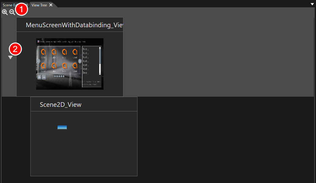
<div drawio-diagram="8824"><img src="https://doc316en.candera.eu/uploads/images/drawio/2025-12/drawing-4-1764895240.png" alt="drawing-4-1764895240.png"/></div>

<table id="bkmrk-1-zoom-icon-zooms-th" style="border-collapse:collapse;width:800px;border-width:1px;"><colgroup><col style="width:5.72099%;"></col><col style="width:25.0266%;"></col><col style="width:69.2416%;"></col></colgroup><tbody><tr><td class="align-center">1</td><td>**Zoom icon**</td><td>Zooms the previews of Views in the View Tree.</td></tr><tr><td class="align-center">2</td><td>**Expand/Collapse icon**</td><td>Appears when a View has child Views. Click to toggle the visibility of the child Views.

</td></tr></tbody></table>

### Basic operations

#### Create a new View Tree

Follow these steps to create a new **View Tree**:

1. In **Solution Explorer**, open the context menu at the desired location.
2. Choose **Add &gt; New Item**.
    
    
    - The **Add New Item** dialog opens.
3. In the dialog’s left pane, select **View Tree**, then click **OK**.
    
    
    - The value you enter in **Name** becomes the new View Tree’s name.
4. A new **View Tree** is created in **Solution Explorer**.
5. Double-click the newly created View Tree to launch the **Condition Editor**.

<p class="callout info">For the View Tree you created, you can use <span style="color:rgb(230,126,35);">[the standard operations](https://doc316en.candera.eu/link/46#bkmrk-copy%2C-clone%2C-rename-) </span>in **Solution Explorer** to **copy**, **duplicate**, **delete**, and **rename** it.</p>

#### Place Views

Drag and drop Views that you have defined beforehand in the <span style="color:rgb(230,126,35);">[**View Definition Editor**](https://doc316en.candera.eu/books/view-editor/page/view-definition-editor)</span> onto the View Tree panel.

- Dropping onto a blank area of the View Tree panel places the Views side by side (as peers).
- Dropping onto an existing View places the dropped View as that View’s child.

<p class="callout info">When a parent–child relationship is set between Views, the child View’s event logic is activated in sync when the parent View becomes active.</p>

#### Configuring in Action Chain Editor

For each View placed on the **View Tree**, you can configure its event logic in the [<span style="color:rgb(230,126,35);">**Action Chain Editor**</span>](https://doc316en.candera.eu/books/view-editor/page/action-chain-editor). You can launch the Action Chain Editor in either of the following ways:

- Double-click the View you want to configure.
- Select the View and choose **Open Action Chain Editor** from the context menu.

#### Exported as a Global State Machine

- The information you build on the View Tree (relationships between Views and their transition logic) is exported as a **Global State Machine** when assets are generated.
- The exported state machine is then executed on the engine side via <span style="color:rgb(230,126,35);">[**JumpToView**](https://doc316en.candera.eu/link/582#bkmrk-jump-to-view)</span>-related events/actions to control the actual screen transitions.

# Action Chain Editor

**Action Chain Editor** is a visual editor for composing a **<span style="color:rgb(230,126,35);">[View](https://doc316en.candera.eu/books/view-editor/page/view)</span>**’s event logic on a per-trigger basis. Starting from user input or system events, you can define transitions between Views, play animations, and build complex event-driven behaviors—visually and intuitively—as Action Chain diagrams composed of **Trigger**, **Action**, and **Condition** nodes.

<p class="callout info">Operations on the **Action Chain Editor** panel are available only after you have created a **View** in the <span style="color:rgb(230,126,35);">[**View Tree**](https://doc316en.candera.eu/books/view-editor/page/view-tree)</span>.   
In the Action Chain Editor, a Condition node references the Condition Output created in the <span style="color:rgb(230,126,35);">**[Condition Editor](https://doc316en.candera.eu/books/view-editor/page/condition-editor)**</span>. You must define a Condition Block—and within it the Condition Output that represents the evaluation result—beforehand.  
</p>

### Action Chain Editor panel UI

#### Panel layout

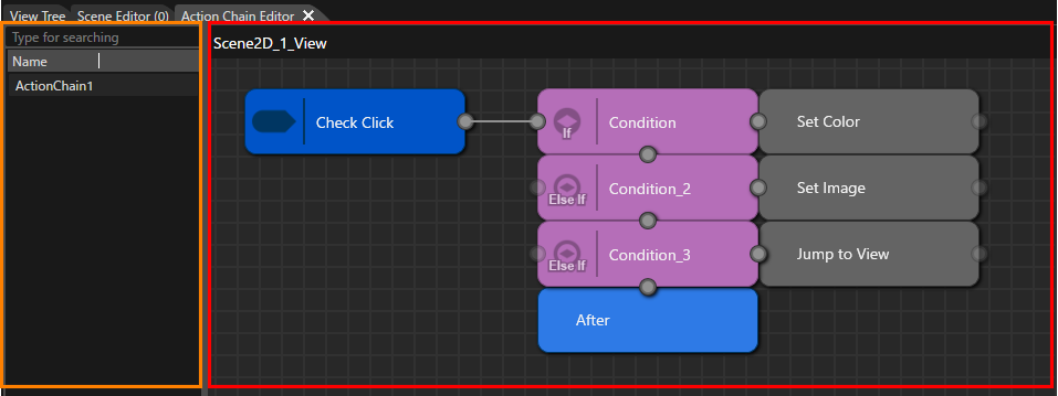
The Action Chain Editor consists primarily of the following two panes.

<p class="callout info">By default, the **Action Chain Editor** panel is hidden. To display it, choose **View &gt; View Editor &gt; Action Chain Editor** from the menu bar.</p>

<div drawio-diagram="8903"><img src="https://doc316en.candera.eu/uploads/images/drawio/2026-01/drawing-4-1768265690.png" alt="drawing-4-1768265690.png"/></div>

<table id="bkmrk-ui-%E9%A0%85%E7%9B%AE-%E8%AA%AC%E6%98%8E-%E5%B7%A6%E3%83%9A%E3%82%A4%E3%83%B3%EF%BC%88%E4%B8%8A%E5%9B%B3%E3%82%AA%E3%83%AC%E3%83%B3%E3%82%B8" style="width:100%;"><thead><tr><th style="width:27.1613%;background-color:rgb(35,111,161);">**<span style="color:rgb(255,255,255);">UI items</span>**</th><th style="width:72.8279%;background-color:rgb(35,111,161);">**<span style="color:rgb(255,255,255);">Description</span>**</th></tr></thead><tbody><tr><td style="width:27.1613%;">**Left pane** (orange frame in the figure above)

</td><td style="width:72.8279%;">Manages multiple **Action Chain** diagrams in a list. You can organize diagrams by feature or by input device, and perform operations such as creating, opening, renaming, and deleting.

</td></tr><tr><td style="width:27.1613%;">**Right pane** (red frame in the figure above)

</td><td style="width:72.8279%;">The workspace for editing the selected **Action Chain** diagram. Place and connect **Trigger**, **Action**, and **Condition** nodes to define the processing flow.

</td></tr></tbody></table>

##### Left pane

On the left pane, you can use the context menu to perform the following:

<table id="bkmrk-%E3%83%A1%E3%83%8B%E3%83%A5%E3%83%BC-%E8%AA%AC%E6%98%8E-new-diagram-" style="width:100%;"><thead><tr><th style="width:18.4777%;background-color:rgb(35,111,161);"><span style="color:rgb(255,255,255);">Menu</span></th><th style="width:81.5115%;background-color:rgb(35,111,161);">**<span style="color:rgb(255,255,255);">Description</span>**</th></tr></thead><tbody><tr><td style="width:18.4777%;">New Diagram</td><td style="width:81.5115%;">Create a new Action Chain diagram.</td></tr><tr><td style="width:18.4777%;">Open</td><td style="width:81.5115%;">Open the diagram selected in the left pane.</td></tr><tr><td style="width:18.4777%;">Rename</td><td style="width:81.5115%;">Change the name of the diagram selected in the left pane.</td></tr><tr><td style="width:18.4777%;">Delete</td><td style="width:81.5115%;">Delete the diagram selected in the left pane.</td></tr></tbody></table>

##### Right pane

On the right pane of the Action Chain diagram, you can place and connect the following nodes from the context menu. The properties of each node placed on the diagram can be edited in the Properties panel.

<table id="bkmrk-%E3%83%A1%E3%83%8B%E3%83%A5%E3%83%BC-%E8%AA%AC%E6%98%8E-add-trigger-" style="width:100%;height:425.483px;"><thead><tr style="height:29.7017px;"><th style="width:18.4724%;background-color:rgb(35,111,161);height:29.7017px;"><span style="color:rgb(255,255,255);">Menu</span></th><th style="width:81.5168%;background-color:rgb(35,111,161);height:29.7017px;">**<span style="color:rgb(255,255,255);">Description</span>**</th></tr></thead><tbody><tr style="height:63.3097px;"><td style="width:18.4724%;height:63.3097px;">Add Trigger</td><td style="width:81.5168%;height:63.3097px;">Add Trigger Select a trigger node that serves as the entry point of the Action Chain.

Use this menu to select the **Condition behavior** or **Behavior Building Block** (including Condition behaviors) that you want to use as the trigger. You can also create it by dragging and dropping a Condition behavior from the toolbox.

</td></tr><tr style="height:63.3097px;"><td style="width:18.4724%;height:63.3097px;">Add Action</td><td style="width:81.5168%;height:63.3097px;">Places a node that represents the action to execute.

Select the **Action behavior** (for example, switching Views or playing an animation) or a **Behavior Building Block** (including Action behaviors) that you want to use. You can also create it by dragging and dropping an Action behavior from the toolbox.

</td></tr><tr style="height:74.148px;"><td style="width:18.4724%;height:74.148px;">Add Condition</td><td style="width:81.5168%;height:74.148px;">Select the **ConditionOutput** created in the <span style="color:rgb(230,126,35);">**[Condition Editor](https://doc316en.candera.eu/books/view-editor/page/condition-editor)**</span>, or a **Behavior Building Block** (including Condition behaviors). Branches the subsequent flow (true/false) based on the evaluation result.

- If no ConditionOutputs are defined in the *Condition Editor*, this menu is not shown.
- ConditionOutputs that are not configured correctly are not listed in this menu

</td></tr><tr style="height:46.5057px;"><td style="width:18.4724%;height:46.5057px;">Add After</td><td style="width:81.5168%;height:46.5057px;">Defines processing that must run afterwards regardless of whether the condition evaluated to true or false. Use this to express post-processing or common flows.

</td></tr><tr style="height:29.7017px;"><td style="width:18.4724%;height:29.7017px;">Add Else</td><td style="width:81.5168%;height:29.7017px;">Used together with **Add Condition** menu to construct an if/else if/else logic structure.</td></tr><tr style="height:29.7017px;"><td style="width:18.4724%;height:29.7017px;">Copy</td><td style="width:81.5168%;height:29.7017px;">Shown when a node is selected on the right pane. Copies the selected node.</td></tr><tr style="height:29.7017px;"><td style="width:18.4724%;height:29.7017px;">Paste</td><td style="width:81.5168%;height:29.7017px;">Shown after performing Copy or Cut. Places a duplicate of the copied/cut node onto the diagram.

</td></tr><tr style="height:29.7017px;"><td style="width:18.4724%;height:29.7017px;">Cut</td><td style="width:81.5168%;height:29.7017px;">Shown when a node is selected on the right pane. Cuts the selected node.</td></tr><tr style="height:29.7017px;"><td style="width:18.4724%;height:29.7017px;">Delete</td><td style="width:81.5168%;height:29.7017px;">Shown when a node is selected on the right pane. Deletes the selected node.</td></tr></tbody></table>

### Basic operations

#### Create a new diagram

To create a new Action Chain diagram, first select the target View in the **View Tree** panel.

1. In **View Tree**, select the View you want to define an Action Chain for.
2. Open the **Action Chain Editor** using either of the following:
    
    
    - Double-click the target View
    - Right-click the target View and choose **Open Action Chain Editor**.
3. In the **left pane** of the Action Chain Editor, open the context menu and select **New Diagram**.
    
    
    - A new **Action Chain** appears in the left pane.
    - Rename the diagram as needed.

#### Place a Trigger node

In an Action Chain diagram, start by placing a **Trigger** node that specifies “when to run.” The trigger hands off execution to the subsequent **Condition** group.

Place it on the right pane in either of the following ways:

- Right-click the right pane and choose **Add Trigger**, then select the trigger behavior to use from the list.
- Drag the desired trigger behavior from the **toolbox** onto the right pane.

#### Place ConditionOutput and Action nodes

A **ConditionOutput** (defined within a Condition Block) and an Action together represent one “if line.”

<p class="callout info">A **ConditionOutput** node must be created beforehand in the <span style="color:rgb(230,126,35);">**[Condition Editor](https://doc316en.candera.eu/books/view-editor/page/condition-editor)**</span>.</p>

- On the **right pane**, open the context menu and choose **Add Condition** to place a ConditionOutput node.
    
    
    - This node references a ConditionOutput created in the <span style="color:rgb(230,126,35);">**[Condition Editor](https://doc316en.candera.eu/books/view-editor/page/condition-editor)**</span>.
- For processing that should run when the ConditionOutput evaluates to **true**, choose **Add Action** to place an **Action** node. 
    - Placing an Action node immediately to the **right** of a ConditionOutput has the following meaning:  
        `Condition_1 + Action_1 → if (Condition_1) { Action_1(); }`
- Placing another ConditionOutput **vertically below** an existing ConditionOutput creates an **if / else if / else** block that is evaluated **top to bottom** (see the next section, “if/else if/else logic”).

#### if/else if/else logic

In an Action Chain diagram, you express `if / else if / else` by how you arrange **ConditionOutputs** and **Actions**.

- **Single row (side by side)**
    
    
    - Placing a **ConditionOutput** on the left and an **Action** on the right represents `if (Condition_X) { Action_X(); }` (see <span style="color:rgb(230,126,35);">[Case 2](#bkmrk-case-2%3A-nested-if-%28s)</span> below).
- **Stacked conditions in the same column**
    
    
    - From top to bottom, the rows are evaluated as `if` → `else if` → `else` (see <span style="color:rgb(230,126,35);">[Case 3](#bkmrk-case-3%3A-exclusive-br)</span>).
    - Rows that include a **ConditionOutput** correspond to `if`/`else if`, and a row that has only an **Action** corresponds to `else` (see <span style="color:rgb(230,126,35);">[Case 6](#bkmrk-case-6%3A-three-way-br)</span>).
- **Nested if**
    
    
    - Connecting from an **Action** node to another **ConditionOutput** node creates a nested `if`, which evaluates an additional condition after that Action (see <span style="color:rgb(230,126,35);">[Cases 2](#bkmrk-case-2%3A-nested-if-%28s)</span> and <span style="color:rgb(230,126,35);">[Case 7](#bkmrk-case-7%3A-nested-if-%28a)</span>).

#### Using After nodes

An **After** node is used to gather the “exits” of multiple branches into one.

- If you connect lines from multiple **Condition** rows to the same **After** node, all of those branches merge at that After.
    
    
    - Any **Action** placed to the right of an **After** node will always run next, regardless of which path was taken.
- If you insert an **After** node and then start a new **Condition** group, you can build a structure that “executes multiple independent `if` blocks in sequence under the same trigger” (see Cases 4 and 5 below).
- Even if an **After** node is present, processing ends there unless you connect an outgoing line. Therefore, placing an After node is not mandatory; however, adding one helps to: 
    - Clearly mark the end of a branching block, and
    - Make it easier to add common post-processing later.

### Action Chain Configuration Examples

This section shows how node arrangements on the **Action Chain** diagram (right pane) correspond to example **if** statements.

#### Case 1: Basic single-condition **if**

The simplest Action Chain: one condition and one action.

- A trigger (**Check Click**) detects the event; if the condition evaluates to **true**, a single action (**Set Color**) runs.


<div drawio-diagram="8896"><img src="https://doc316en.candera.eu/uploads/images/drawio/2026-01/drawing-4-1768265118.png" alt="drawing-4-1768265118.png"/></div>

```c++
if (Check Click)
{
    Set Color();
}

```

#### Case 2: Nested **if** (side-by-side layout)

This configuration shows how to represent a nested `if` that evaluates another condition within the branch of an existing condition.

Arrange the nodes in a single row as: **Trigger -&gt; Condition -&gt; Action (Set Color) -&gt; Condition\_2 -&gt; Action (Set Color)**.

- First, if **Condition** is true, run **Set Color**.
- Then evaluate **Condition\_2**; if it is true, also run **Set Color**.

With this **horizontal (side-by-side) layout**, you can express “an `if` inside an `if`” as a nested conditional that is evaluated after the preceding **Action**.

<div drawio-diagram="8897"><img src="https://doc316en.candera.eu/uploads/images/drawio/2026-01/drawing-4-1768265141.png" alt="drawing-4-1768265141.png"/></div>

```c++
if (Check Click)
{
    if (Condition)
    {
        Set Color();

        if (Condition_2)
        {
            Set Color();
        }
    }
}

```

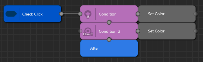
#### Case 3: Exclusive branching (if / else if)

This configuration shows how to evaluate multiple conditions for the same event **exclusively** (`if / else if`) so that **only one** action runs.

Place two rows—**Condition** and **Condition\_2**—stacked vertically **one column to the right of the Trigger**, and place their corresponding Actions (**Set Color** / **Set Color**) to the right of each row. This represents:

- Upper row: `if (Condition) { SetColor(); }`
- Lower row: `else if (Condition_2) { SetColor(); }`

To make the branch’s **common exit** explicit, place a single **After** node at the end of the block formed by **Condition** and **Condition\_2**. The After node denotes “the exit for this `if`/`else if` group,” and all subsequent processing should connect to the **right** of the After node. With this layout, it is visually clear that **regardless of which condition is met**, the flow ultimately **merges** into the same continuation.

<div drawio-diagram="8898"><img src="https://doc316en.candera.eu/uploads/images/drawio/2026-01/drawing-4-1768265197.png" alt="drawing-4-1768265197.png"/></div>

```c++
if (Check Click)
{
    if (Condition)
    {
        Set Color();
    }
    else if (Condition_2)
    {
        Set Color();
    }
}

```

#### Case 4: Two independent **if** blocks under the same Trigger

This configuration evaluates two Conditions **independently and in sequence** within a single Trigger.

- The **After** placed beneath the `Condition + Set Color` row is a mandatory exit: the flow passes through it **whether `Condition` is true or false**, and then proceeds to **`Condition_2`**. 
    - As a result, `Condition_2` is **always** evaluated, regardless of the outcome of `Condition`.
- The **After\_1** placed beneath the `Condition_2 + Set Color` row marks the **end** of the entire chain.

By contrast with **Case 3**, where stacking ConditionOutputs in the same column and using a **single After** yields **exclusive branching** (i.e., the next Condition is checked **only if** the previous one was false), **Case 4** inserts an intermediate **After** between the rows so that **both `if` blocks are evaluated** in order.

<div drawio-diagram="8899"><img src="https://doc316en.candera.eu/uploads/images/drawio/2026-01/drawing-4-1768265248.png" alt="drawing-4-1768265248.png"/></div>

```c++
if (Check Click)
{
    if (Condition)
    {
        Set Color();
    }
    if (Condition_2)
    {
        Set Color();
    }
}

```

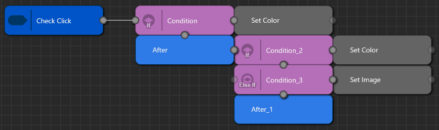
#### Case 5: Independent **if** + subsequent **if/else if** group

This configuration combines a single standalone `if` followed by an `if / else if` branching group under the same Trigger.

- **Row 1** (`Condition + Set Color`) corresponds to:  
    `if (Condition) { SetColor(); }`
    
    
    - The **After** directly beneath Row 1 is a mandatory exit. The flow passes through it **whether `Condition` is true or false**, and then proceeds to the group formed by **Condition\_2** and **Condition\_3**.
- **Rows 2 and 3** (`Condition_2 + Set Color`, `Condition_3 + Set Image`) represent:  
    `if (Condition_2) { SetColor(); } else if (Condition_3) { SetImage(); }`
    
    
    - When **Condition\_2** is true, **only** `SetColor()` runs; **only when it is false** is **Condition\_3** evaluated.
- The **After\_1** beneath these two rows is the **common exit** for the `if / else if` group.

Compared with **Case 4**, where both **Condition\_1** and **Condition\_2** were independent `if` blocks, **Case 5** has an **independent `if`** for **Condition\_1**, followed by an **`if / else if` group** formed by **Condition\_2** and **Condition\_3**.

<div drawio-diagram="8900"><img src="https://doc316en.candera.eu/uploads/images/drawio/2026-01/drawing-4-1768265305.png" alt="drawing-4-1768265305.png"/></div>

```c++
if (Check Click)
{
    if (Condition)
    {
        Set Color();
    }
    if (Condition_2)
    {
        Set Color();
    }
    else if (Condition_3)
    {
        Set Image();
    }
}

```

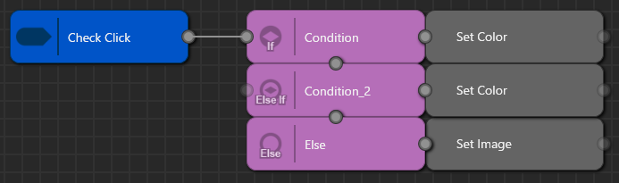
#### Case 6: Three-way branching (if / else if / else)

This configuration shows a classic **exclusive** branch with three paths under a single Trigger.

- **Row 1: “Condition + Set Color”**  
    Corresponds to `if (Condition) { SetColor(); }`.  
    **Set Color** runs only when **Condition** is true.
- **Row 2: “Condition\_2 + Set Color”**  
    Corresponds to `else if (Condition_2) { SetColor(); }`.  
    **Set Color** runs only when **Condition** is false **and** **Condition\_2** is true.
- **Row 3: “Else + Set Image”**  
    Corresponds to `else { SetImage(); }`.  
    **Set Text** runs only when both **Condition** and **Condition\_2** are false.

The key point is that **exactly one** Action runs: evaluation proceeds **top to bottom** and executes the Action on the **first** row whose condition matches.

<div drawio-diagram="8901"><img src="https://doc316en.candera.eu/uploads/images/drawio/2026-01/drawing-4-1768265354.png" alt="drawing-4-1768265354.png"/></div>

```c++
if (Check Click)
{
    if (Condition)
    {
        Set Color();
    }
    else if (Condition_2)
    {
        Set Color();
    }
    else
    {
        Set Image();
    }
}

```


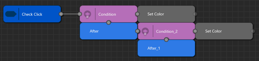
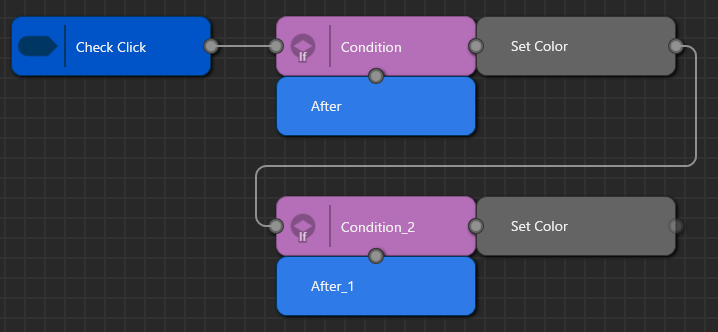
#### Case 7: Nested `if` (After-based layout)

This configuration represents a nested `if` where one **ConditionOutput** is evaluated only inside the branch of another.

- The flow goes from the Trigger **Check Click** to **Condition**—this is the outer `if (CheckClick)`.
- The row **“Condition + Set Color”** corresponds to `if (Condition) { SetColor(); … }`.
- Because there is a connector from **Set Color** down to **Condition\_2**, **Condition\_2** is evaluated **only when `Condition` is true**. If `Condition` is false, the flow does **not** proceed to `Condition_2`.
- The lower row **“Condition\_2 + Set Color”** corresponds to `if (Condition_2) { SetColor(); }`. Thus, **only when both** `Condition` **and** `Condition_2` are true do `SetColor()` and then `SetColor()` run in sequence.
- **After** and **After\_1** serve as visual **exits/merge points** for the **Condition** block and the **Condition\_2** block, respectively.

In contrast to **Case 4**, where two ConditionOutputs are treated as **two independent `if`s** that are both evaluated, **Case 7** places **Condition\_2** entirely **inside** **Condition**, forming a classic **nested `if`** structure.

<div drawio-diagram="8902"><img src="https://doc316en.candera.eu/uploads/images/drawio/2026-01/drawing-4-1768265406.png" alt="drawing-4-1768265406.png"/></div>

```c++
if (Check Click)
{
    if (Condition)
    {
        Set Color();

        if (Condition_2)
        {
            Set Color();
        }
    }
}

```

# Condition Editor

The **Condition Editor** is a visual editor for defining conditional logic that branches the processing flow based on input devices and the solution state. Conditional logic is managed in **Condition Blocks**. Within a Condition Block, you define one or more **ConditionOutput**s that represent the evaluation results (true/false). ConditionOutputs can be referenced from Condition nodes in the <span style="color:rgb(230,126,35);">**[Action Chain Editor](https://doc316en.candera.eu/books/view-editor/page/action-chain-editor)**</span>. They can also be assigned to the Condition property of behaviors and Fusion, allowing the same conditional logic to be reused in multiple places across the solution.

### Tool UI overview

#### Panel layout

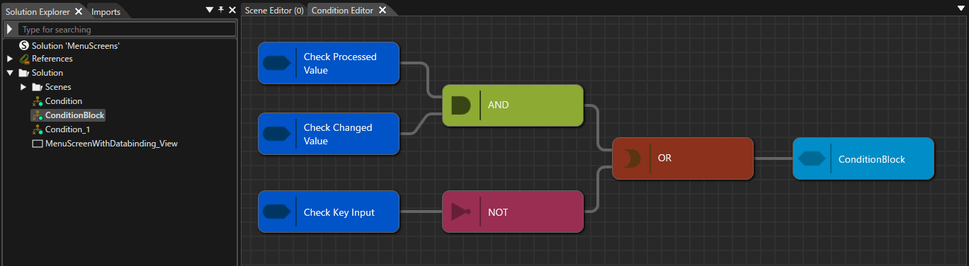
Double-click any **Condition Block** in **Solution Explorer** to open the **Condition Editor** panel. On this panel, you build a logical expression by placing and connecting **Check / AND / OR / NOT** nodes. Condition Blocks you create here can be referenced from the <span style="color:rgb(230,126,35);">[**Action Chain Editor**](https://doc316en.candera.eu/books/view-editor/page/action-chain-editor)</span>.

<p class="callout info">By default, the **Condition Editor** panel is hidden. To display it, choose **View &gt; View Editor &gt; Condition Editor** from the menu bar.</p>


<div drawio-diagram="8823"><img src="https://doc316en.candera.eu/uploads/images/drawio/2025-12/drawing-4-1764895088.png" alt="drawing-4-1764895088.png"/></div>

On the **Condition diagram**, you can place and connect nodes via the context menu. When you open a **Condition Block** in the Condition Editor, a default ConditionOutput node is placed automatically on the diagram. ConditionOutputs can be added or deleted as needed. The properties of nodes placed on the diagram can be edited in the **Properties panel**.

<p class="callout info">A **ConditionOutput** node represents the evaluation result (true/false) of the logical expression defined in the **Condition Block**. The logical expression you create in the Condition Editor is stored under each **ConditionOutput** node name and can be referenced from the **Action Chain Editor**. The same ConditionOutput can also be assigned to the Condition property of behaviors and **Fusion**.</p>

<table id="bkmrk-%E3%83%8E%E3%83%BC%E3%83%89%E7%A8%AE%E5%88%A5-%E8%AA%AC%E6%98%8E-add-check-%E6%9D%A1" style="width:800px;height:139.517px;border-collapse:collapse;"><thead><tr style="height:29.7017px;"><th style="width:27.2767%;height:29.7017px;background-color:rgb(35,111,161);"><span style="color:rgb(255,255,255);">**Node type**</span></th><th style="width:72.7124%;height:29.7017px;background-color:rgb(35,111,161);"><span style="color:rgb(255,255,255);">**Description**</span></th></tr></thead><tbody><tr style="height:63.3097px;"><td style="width:27.2767%;height:63.3097px;">Add Check</td><td style="width:72.7124%;height:63.3097px;">Select a **Check** node that serves as the entry point for configuring the condition expression.

Use this menu to select the **Condition behavior** or **Behavior Building Block** (including Condition behaviors) that you want to use as the starting point. You can also create it by dragging a Condition behavior from the toolbox onto the diagram.

</td></tr><tr style="height:46.5057px;"><td style="width:27.2767%;height:46.5057px;">Add AND / OR / NOT</td><td style="width:72.7124%;height:46.5057px;">These are logical operator nodes that combine multiple **Check** nodes and sub-conditions. Use **AND / OR / NOT** to express composite conditions.</td></tr><tr><td style="width:27.2767%;">Add OUTPUT</td><td style="width:72.7124%;">Add a new **ConditionOutput** node.</td></tr><tr><td style="width:27.2767%;">Copy / Cut / Delete / Paste</td><td style="width:72.7124%;">This menu becomes available when a node on the diagram is selected. It lets you **copy**, **cut**, **delete**, and **paste** the selected node.</td></tr></tbody></table>

### Basic operations

#### Create a new Condition Block

Follow these steps to create a new **Condition Block**:

1. In **Solution Explorer**, open the context menu at the desired location.
2. Choose **Add &gt; New Item**.
    
    
    - The **Add New Item** dialog opens.
3. In the dialog’s left pane, select **Condition Block**, then click **OK**.
    
    
    - The value you enter in **Name** becomes the new Condition Block’s name.
    - The [<span style="color:rgb(230,126,35);">**Category** setting determines</span>](#bkmrk-create-a-new-conditi) which category (location) the Condition Block is registered under in the toolbox.
4. A new **Condition Block** is created in **Solution Explorer**.
    
    
    - At the same time, the Condition Block you created is added to **Behaviors** in the **toolbox**.
    - For details on where it is placed, see <span style="color:rgb(230,126,35);">[Reusing a Condition Block](#bkmrk-reusing-a-condition-)</span> below.
5. Double-click the newly created Condition Block to launch the **Condition Editor**.
    
    
    - On the Condition Editor panel diagram, there is a ConditionOutput node named **Condition**.

#### Reusing a Condition Block

The created ConditionBlock and each ConditionOutput within the ConditionBlock are registered in the toolbox. By dragging and dropping a ConditionBlock or ConditionOutput from the toolbox, you can reuse the same condition logic in the following places:

- **Condition Editor**: Place it as a Check node that references an existing ConditionOutput.
- **Action Chain Editor**: Assign it to the **Condition** property of a Condition node.
- **Behaviors/Fusion**: Assign the ConditionOutput to the **Condition** property of the corresponding behavior.

Also, where a **Condition Block** appears within the toolbox’s Behaviors categories depends on whether the Category property is set.

- If **Category is set**: A category with the same name is added under the toolbox’s Behaviors, and the Condition Block is shown there.
- If **Category is not set**: The Condition Block is automatically shown under an appropriate category in the toolbox’s Behaviors, depending on the conditions you configured.

To check which category it appears in, select the target Condition Block in the Solution Explorer, then see **General &gt; Category** in the Properties panel.

<p class="callout info">For the created Condition Block and the **ConditionOutput** nodes placed within the Condition Block, you can use <span style="color:rgb(230,126,35);">[the standard operations](https://doc316en.candera.eu/link/46#bkmrk-copy%2C-clone%2C-rename-)</span> in **Solution Explorer** to copy, duplicate, delete, and rename them.</p>

#### Creating a Condition diagram

1. In **Solution Explorer**, double-click any Condition Block.
    
    
    - The **Condition Editor** panel opens.
    - On the panel, there is a ConditionOutput node named **Condition**.
2. On the right pane, open the context menu, choose **Add Check**, and select the Condition behavior to use.
    
    
    - It is placed on the diagram as a **Check** node.
3. Place **AND / OR / NOT** nodes as needed and build the logical expression.
4. As needed, add **AND / OR / NOT** nodes and connect the **Check** nodes to construct the expression.
5. Connect the **ConditionOutput** node at the end of the diagram.
    
    
    - Logical expressions created in the Condition Editor are saved under the name of each ConditionOutput node and can be referenced from Condition nodes in the Action Chain Editor.
    - The same ConditionOutput can also be assigned to the **Condition** property of the corresponding behaviors/Fusion for reuse.