# Basic Operation
### State Machine in the Menu Bar
The **State Machine** menu in the menu bar, offers the following options.
| New State Machine... | Select this option to create a new State Machine. For details, refer to [How to Create a new State Machine](#bkmrk-%E3%82%B9%E3%83%86%E3%83%BC%E3%83%88%E3%83%9E%E3%82%B7%E3%83%B3%E3%81%AE%E6%96%B0%E8%A6%8F%E4%BD%9C%E6%88%90%E6%96%B9%E6%B3%95). |
| Attach... | Connect to the currently running CGI Panel.
After selecting this option, the **Attach to application** dialog will be displayed. Enter the IP address and port number of the target CGI Panel. This option is also used when utilizing the Debugger panel. For more details, please refer to [State Machine Debugger](https://doc316en.candera.eu/books/state-machine/page/debugger). |
| Validate Active State Machine | Select this option to perform validation on the currently active State Machine. |
### How to Create a New State Machine
There are two ways to create a new State Machine:
#### 1. Create State Machine in Solution Explorer
1. In the **Solution Explorer**, right click any folder (e.g. Solution).
- The **context menu** will open.
2. From this menu, select **Add** > **New Item...**
- The **Add New Item** dialog appears.
3. In the list on the left, select **StateMachine**, then configure the settings displayed on the right side of the dialog. Confirm your configuration by clicking **OK**.
- A new **StateMachine** item will be created in the selected location within the **Solution Explorer**.
#### 2. Create State Machine via the Menu
1. From the menu bar, select **State Machine** > **New State Machine...** .
- The **Add New State Machine** dialog appears.
2. Configure the available settings (e.g. location, name) in the dialog and click **OK**.
- A new **State Machine** item will be created in the selected location within the **Solution Explorer**.
**Multiple State Machines** can be created using the [Multiple Clones ](https://doc316en.candera.eu/books/scene-design/page/manage-nodes#bkmrk-clone%2C-delete%2C-renam)approach in the Solution Explorer.
Each **State Machine** is associated with a specific **scope** defined by its placement. For example, you can create a different State Machine for each **scene** to manage behavior according to scope.
#### Adding a State Machine to a Node (State Machine behavior)
When a State Machine is created for a node in the scene tree, it is automatically associated with that node. Once the association is complete, the State Machine can be configured using the State Machine Editor.
1. In the Scene Tree panel, right click any node of the scene tree.
- The context menu will open.
2. From this menu, select **Add State Machine...**
- The **Add New State Machine** dialog appears.
3. Configure the settings in the dialog and click **OK.**
- A new **State Machine** item will be created in the selected location within the **Solution Explorer**.
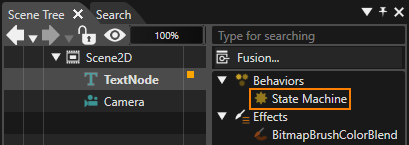
- Additionally, this State Machine appears in the **extra scene tree** of the associated node (see figure below), as it functions as a **State Machine behavior**.
A State Machine created like this is automatically connected as a [State Machine behavior](https://doc316en.candera.eu/books/controls-and-behaviors/page/state-machine-behaviors) in the extra scene tree of the target node. This connection allows the State Machine to receive all events generated by the target node and trigger the appropriate action based on the predefined logic. This mechanism allows for more intuitive and efficient control by linking visual elements (nodes) with behavioral logic (State Machines).
### StateMachine Properties
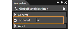
Each State Machine can operate either as a **global** or a **local** State Machine. When you create a new, empty Scene Composer solution, a **global State Machine** is included by default. Any **newly created State Machine** is a **local State Machine** unless you explicitly enable the **IsGlobal** property (see figure below).
Multiple GlobalStateMachines can be set up as needed. This capability allows you to manage complex, solution-wide behavior by coordinating logic that applies across all scenes.
#### Global State Machine
A **Global State Machine** is a State Machine that applies to the **entire solution**. It is active across **all scenes** and begins operating automatically when the solution starts.
- If an event occurs on any node in the Scene Tree and is **not handled by a Local State Machine**, the event is forwarded to the **Global State** Machine, which can then process it according to its defined logic.
- You can configure **multiple Global State Machines**. Each of them can receive and handle events that were not processed by any Local State Machines, enabling flexible, solution-wide control and coordination of behavior.
#### Local State Machine
A **Local State Machine** is a State Machine that is explicitly associated with a specific **node** (an element within the application).
- Local State Machines receive **all events** generated by the node they are connected to.
- You can configure **multiple Local State Machines** for the same node. If an event is **not handled** by any of these Local State Machines, it is passed on to other Local State Machines and ultimately to any **Global State Machines**.
A newly created State Machine is a **Local State Machine by default**. To convert it into a **Global State Machine**, enable the **Is Global** option as described above.
### Priority of Transitions
When multiple Transitions originate from the same State, their **priority** can be configured in two ways. The State Machine evaluates Transition conditions **in order of priority**, and the first Transition whose condition evaluates to *true* is executed.
This mechanism is particularly useful when multiple Transitions share the **same triggering condition**, as it allows you to clearly define which Transition should take precedence and ensures predictable, well-controlled behavior.
#### Settings on the State/Transition view
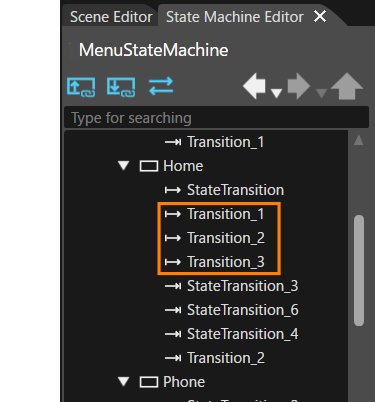
Transitions are displayed in a **tree view** in the upper-left corner of the **State Machine Editor**. In this tree view, Transitions are ordered **from top to bottom according to their priority** - the Transition at the top has the highest priority, and the one at the bottom has the lowest.
You can easily change the priority by **dragging and dropping** Transitions within the tree view. For example, in the configuration highlighted in orange in the figure below, **Transition\_1** has the highest priority and **Transition\_3** has the lowest priority.
#### Settings on the Properties panel
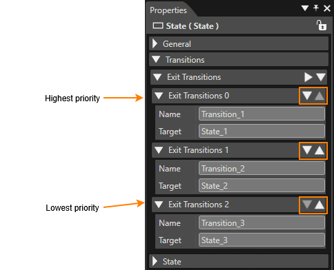
Transitions pointing away from a certain State are called exit transitions. All exit transitions for a certain State are displayed in the properties panel in the **Transitions** > **Exit Transitions** section. In this list, Transitions are displayed **from the top to bottom in order of priority**, with the highest-priority Transition at the top.
You can easily adjust the priority using the **Move Item Up** and **Move Item Down** icons (orange-highlighted area in the figure).
### Add an Element
Each element available in the **State Machine Editor** top toolbar can be added to the diagram using **drag-and-drop**. When placing elements, observe the following restrictions:
- Only **one Initial State** can be placed in each State Machine.
- **History States**, **Entry Points**, and **Exit Points** can be placed **only inside a Subchart**.
These constraints ensure correct State Machine structure and prevent invalid configurations.
### Add a Transition
Interconnecting States with Transitions is a two-step process:
1. **Drag and Drop a Transition**
Drag a **Transition** from the top toolbar and drop it onto the **source State**, releasing the mouse button.
2. **Select the destination State**
Move the mouse towards the **destination State**. As you do so, a Transition arrow will stretch from the source State to the mouse cursor. Drag the arrow onto to the destination State and complete the connection with a mouse click.
This procedure establishes a Transition linking the selected source State to the chosen destination State.
### Transition Inflection Points
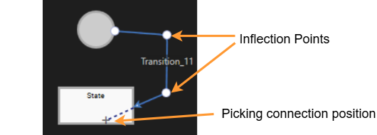
You can add an Inflection Point to the location you click by holding down the **Ctrl** key and clicking on the Transition in the diagram. Adding an Inflection Point allows you to adjust the shape of the Transition line, giving you more control over how the Transition is visually routed within the diagram.
### Changing Element Size
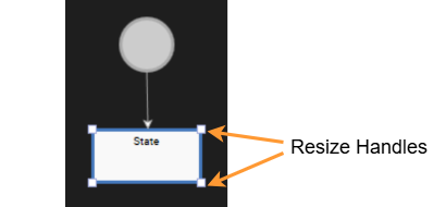
**State**, **History State**, **Subchart** and **Note** elements can be resized freely within the diagram. After placing the element on the canvas, you can adjust its size it by dragging the **resize handles** with the mouse.
### Deleting an element
Elements placed on the State Machine Editor diagram can be deleted in the following ways:
- **Delete from the diagram
**Select the element on the diagram and press the **Delete** key on your keyboard.
- **Delete from the editor tree (State/Transition view)** In the **editor tree**, select the element you want to remove, then either right-click and choose **Delete** from the context menu or press the **Delete** key on your keyboard.
### Subchart
In addition to dragging and dropping a **Subchart** from the top toolbar onto a diagram, you can also create a Subchart by **converting it from an existing State**.
##### Converting to Subchart
A State can be converted to a Subchart by selecting **Convert to Subchart** from the context menu after selecting the State. The original State name is retained after the conversion, but it can be renamed as needed.
### Display and Placement of Entry and Exit Points
**Entry Points** and **Exit Points** can be positioned along the **edges of the Subchart**, clearly defining the flow in and out of the Subchart. When viewing the Subchart on a diagram, these points are also visually indicated, making it easier to grasp the overall flow.
Entry and Exit Points can be **freely rearranged** along the subchart's edge. Thoughtful placement of these points improves readability, enhances structural clarity, and contributes to a more intuitive State Machine design.
### Note
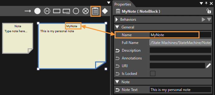
You can add Note to your diagrams in the State Machine Editor. To insert a Note, drag the **Note** element from the State Machine Editor toolbar and drop it onto the diagram.
Note can be **resized** in the same way as States - simply drag the **resize** handles to adjust their dimensions. The **Note titles** can be edited in the Properties panel. Clicking on a Note switches it into **text-editing mode** allowing you to modify its content directly on the diagram.
### Design Options
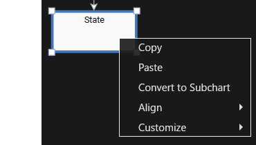
When right-clicking on a selected **State** or **Transition** on a diagram in the **State Machine Editor**, a context menu appears.
| Copy | Copies the selected elements. The copied elements can be pasted onto the diagram using the Paste operation. |
| Paste | Pastes the copied elements onto a diagram. Note that Transitions are only pasted if both the source and destination States are included in the copied selection. |
| Convert to Subchart | Convert the selected State to a Subchart. See [here](#bkmrk-state-subchart) for details. |
| Align | When multiple items are selected,their positions on the diagram can be aligned for consistent layout and improved readability.
Available alignment options include: left, center, right, top, middle, bottom. Additionally, **Distribute Horizontal** and **Distribute Vertical** can be used to evenly space selected items, helping keep the diagram clean and well-organized.
|
| Customize | Decorate the selected State by applying an **image** or filling it with a custom color. For details, please refer to [Changing Styles](#bkmrk-changing_styles).
|
#### Changing Styles
The Scene Composer State Machine Editor allows you to customize States and Transitions using background images and color settings. Applying visual styling can improve the readability of the State Machine diagram and enhance its intuitiveness, specially in complex designs.
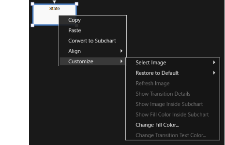
| From Solution Explorer... | The **Choose Item** dialog opens, allowing you to select any image of the Scene Composer solution. Note that you can only select images that have been imported into the solution beforehand. |
| From Local File... | Opens the **Windows OS Select File** dialog, allowing you to choose a local image file from your file system. |
##### Restore to Defaults
Restores the **default settings** for elements that support design customization options. You can choose which defaults to restore by selecting an option from the available menu.
| All | Resets all design settings for the selected element back to their default values. |
| Image | Restores only the element's background to its default setting. |
| Fill Color | Restores only the element's fill color to its default setting. |
| Transition Text Color | Restores only the Transition text color to its default setting.
|
| Transition Details Visibility | Restores only the Transition detail visibility settings to its default. |
| Connection Type | Restores only the Transition connection type (line type) to its default setting. (The default settings for Transition connection types can be found in [Preferences](https://doc316en.candera.eu/books/preferences/page/state-machine)).
|
##### Refresh Image
This option is only available when an image is already assigned to the target State. Reloads the image from the file or captures a new screenshot from the scene/camera.
##### Show Transition Details
When this option is enabled, the transition's name **and** details are displayed next to the transition arrow. When disabled, only the transition's name is displayed.
#####
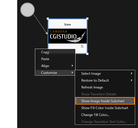
Show Image Inside Subchart
This option is only available for a Subchart State. If this option is enabled, the image set for the State is displayed in the Subchart as background image.
#####
Show Fill Color Inside Subchart
This option is also only available for a Subchart State. If the **Change Fill Color** option (described below) is enabled for the Subchart State, turning on this option applies the State's fill color to the Subchart's background.
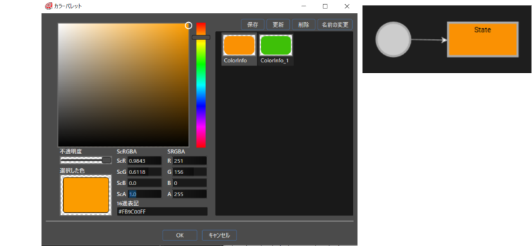
##### Change Fill Color
Allows you to change the background color of the State. Selecting this option opens the **Color Palette** dialog, where you can choose the desired color and confirm with **OK**.
##### Change Transition Text Color
Allows you to change the text color of a Transition's text description. You can change the name text color setting for Transition. Selecting this option opens the **Color Palette** dialog, where you can choose the desired color and confirm with **OK**.
### Using Shortcut Keys
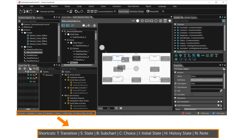
The **State Machine Editor** supports shortcut keys to help you perform some operations more efficiently allowing quick addition and manipulation of elements.
##### Operation Procedure with Shortcut Keys
1. **Mouse over**
Move the mouse cursor to any location or element on the diagram.
2. **Check Available Shortcuts**
All available shortcut keys are displayed in the **lower-left corner** of the Scene Composer window.
3. **Enter a Shortcut Key**
Press one of the displayed shortcut keys on the keyboard to execute the corresponding action.
In the example below, **Transition, State, Subchart, Choice, Initial State, History State**, and **Note** can all be added using shortcut keys.
### Diagram Bird's Eye Function
You can display the **Diagram Bird's Eye** panel by selecting **View > State Machine > Diagram Bird's Eye** from the menu bar.The panel provides an overview of the entire State Machine Editor workspace, allowing you to quickly navigate large or complex diagrams.
For details on viewing and operating this panel, see [Diagram Bird's Eye](https://doc316en.candera.eu/books/solution-handling/page/diagram-birds-eye).
### Undo and Redo
The State Machine Editor supports "**Undo and Redo**" operations, enabling safe and flexible editing of State Machine diagrams.
Please note that **adding, deleting** or **editing** of a Transition's **Inflection Point** is not supported by the Undo and Redo feature.
For more information, see [Undo and Redo Operations](https://doc316en.candera.eu/link/32#bkmrk-page-title).