# State Machine
# Overview
CGI Studio offers an innovative solution for efficiently implementing application logic through its integrated state machine model. This feature enables the visual and intuitive design of program behavior.
The integrated state machine model is supported by both the Graphic Engine and Scene Composer, utilizing existing components such as controls and behaviors.
With Scene Composer, developers can create complex application logic by combining actions, events (trigger conditions), transitions, and multiple state machines. This approach eliminates the need for manual coding and significantly improves development efficiency through an intuitive interface.
Additionally, nodes and behaviors can be cross-referenced between different scenes. These cross-references may impact application logic and should be carefully managed. For detailed information on possible implications of cross-references, please refer to section [Cross-Reference Implications](https://doc316en.candera.eu/books/controls-and-behaviors/page/overview#bkmrk-cross-reference-impl).
# State Machine Panel UI
#### Opening State Machine Editor
You can open the State Machine Editor using one of the following methods.
- **Via the menu**
Navigate to **View > State Machine> State Machine Editor**.
- **Via the Solution Explorer Panel**
In the **Solution Explorer Panel,** browse through the solution and double-click an already existing State Machine.
(In the provided sample solutions, State Machines are located under **Solution > State Machine**)
Once the **State Machine Editor** is open, you can switch between it and other editors (e.g. the Scene Editor) by selecting the corresponding tab.
To adjust display preferences for the **State Machine Editor** panel, open the Preferences dialog via the menu: **File > Preferences...**, then navigate to [Preferences > Environment > State Machine](https://doc316en.candera.eu/books/preferences/page/state-machine).
#### State Machine Editor Panel
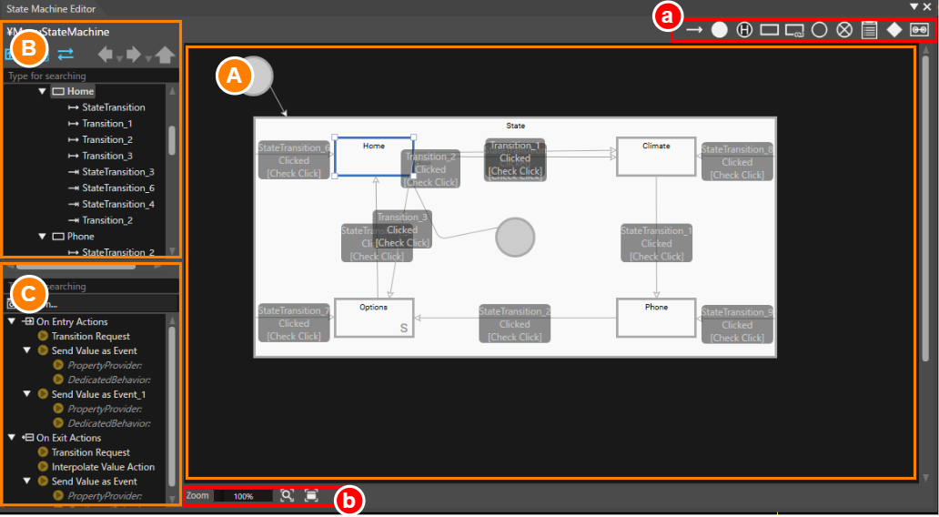
Navigation and rearranging elements in the State Machine Diagram (area A in the image below):
- **Pan the Diagram**:
Drag with the **middle mouse button** to move the State Machine diagram within the editor.
- **Rearrange Elements**:
Use **drag and drop** to reposition individual elements, such as states and transitions, within the diagram.
- **Select Multiple Nodes**:
Click and drag to draw a **selection rectangle** around the elements you want to select.
| A | Diagram | Displays the main workspace for the State Machine Editor. |
| B | State/Transition View | Hierarchically displays all States and Transitions defined in the State Machine Editor. |
| C | Behavior/Fusion Configuration | Displays the behaviors configured for the currently selected element (e.g., State or Transition) in the diagram. By clicking the Fusion button, the Fusion Editor panel will appear, showing Fusion-specific configurations. |
| a | Top Toolbar | Contains icons representing elements for constructing a state machine. These can be dragged onto the diagram to create and configure your state machine. |
| b | Bottom Toolbar | Provides tools for zooming and panning the diagram's display. |
#### State/Transition View
This view displays all elements of the State Machine (states and transitions) in a hierarchical tree format. When you select an element in the tree, the corresponding element is also automatically highlighted in the diagram on the right. This synchronized selection allows you to edit and check each element intuitively and efficiently.
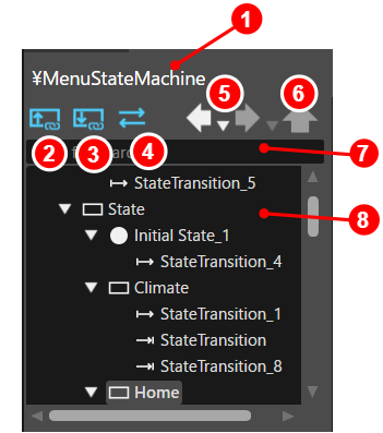
| 1 | State Machine Name | Displays the name of the State Machine currently selected in the Solution Explorer. If a Subchart is open, its fill path is shown.
|
| 2 | show current subcharts only
| Switches the content displayed in the editor tree.
- **Enabled (blue icon):** Displays the entire content of the selected state machine, allowing a comprehensive overview.
- **Disabled (white icon):** Displays only the currently active Subchart as the root of the editor tree. If no Subchart is active, the full content is shown.
|
| 3 | show subchart details
| Switches the Subchart content displayed in the editor tree.
- **Enabled (blue icon):** Displays all contents within the currently active Subchart, providing a detailed view of its structure.
- **Disabled (white icon):** Displays only the active Subchart's immediate elements, focusing on essential information.
|
| 4 | show transitions
| Toggles the visibility of Transitions in the editor tree.
- **Enabled (blue icon):** Displays all Transitions, showing their relationships as child nodes under their source or target.
- **Disabled (white icon):** Hides all Transitions, simplifying the tree display.
|
| 5 | Navigation Buttons | Works similarly to a web browser's "Back" and "Forward" controls. They allow you to browse through the display history of state machines in the diagram, making it easy to revisit previously viewed diagrams.
|
| 6 | Hierarchy Navigation Button | Enables you to switch from a detailed Subchart view back to a higher-level hierarchy view. This feature helps you easily transition between Subchart-specific details and the overall state machine structure, ensuring better navigation and context awareness. |
| 7 | Search Field | Allows you to quickly locate States or Transitions within the editor tree by entering keywords. When a match is found, the corresponding element is automatically highlighted in both the editor tree and the diagram. Additionally, its details are displayed in the properties panel for easy review and editing. |
| 8 | Editor Tree | Displays all elements configured in the diagram, such as States, Transitions, and other components, in a hierarchical tree structure. |
#### Behavior/Fusion Configuration
This panel displays the behaviors associated with the currently selected State Machine element (State, Transition, etc.). To configure or edit complex behavior logic, click the **Fusion...** button to open the Fusion Editor.
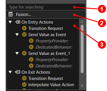
| 1 | Search Field | Allows you to quickly locate behaviors in the Behavior View by entering a string of characters.
If a behavior that includes the keyword you entered is found, it is automatically highlighted and its details are displayed in the Properties panel, enabling easily review and editing.
|
| 2 | Fusion button | Opens the Fusion Editor and displays the Fusion diagram for the selected element (such as State, Transition, etc.). This allows you to configure and edit Fusion-specific configurations.
|
| 3 | Behavior View | Lists all behaviors configured within the currently selected element (State, Transition, etc.).
|
#### Top Toolbar
The toolbar at the top of the diagram provides icons for the elements that make up a State Machine. To add elements such as States, Transitions and other components:
- **Drag** the desired icons from the toolbar.
- **Drop** it into the State Machine diagram.
This intuitive drag-and-drop functionality makes it easy to build and customize complex State Machines
For detailed information about each component, please refer to [Components in State Machine](https://doc316en.candera.eu/books/state-machine/page/components-in-state-machine).

| 1 | [Transition](https://doc316en.candera.eu/link/204#bkmrk-transition) | A **Transition** defines the movement **between States** based on specified conditions and actions. |
| 2 | [Initial State](https://doc316en.candera.eu/link/204#bkmrk-initial-state) | The **Initial State** represents the **starting point** of the State Machine's execution.
|
| 3 | [History State](https://doc316en.candera.eu/link/204#bkmrk-history-state) | The **History State** stores the last State within a Subchart and resumes execution from that state when the Subchart is re-entered. |
| 4 | [State](https://doc316en.candera.eu/link/204#bkmrk-state) | A **State** represents a specific point in the State Machine. Specific actions and conditions can be processed at both when **entering** and **exiting** the state.
|
| 5 | [Subchart](https://doc316en.candera.eu/link/204#bkmrk-subchart) | A **Subchart** is a structural element that groups States and Transitions into a single unit, simplifying the management of complex State Machines. |
| 6 | [Entry Point](https://doc316en.candera.eu/link/204#bkmrk-entry%2Fexit-point) | An **Entry Point** is a pseudo-state that enables controlled entry into a Subchart. |
| 7 | [Exit Point](https://doc316en.candera.eu/link/204#bkmrk-entry%2Fexit-point) | An **Exit Point** is a pseudo-state that enables controlled exit from a Subchart.
|
| 8 | [Note](https://doc316en.candera.eu/link/204#bkmrk-note) | A **Note** is a visual element used to organize and display **supplementary information** and design details related to State Machines. |
| 9 | [Choice](https://doc316en.candera.eu/link/204#bkmrk-design-options) | A **Choice** is used to branch transitions based on conditions. |
| 10 | ViewState | A **ViewState** controls the visibility of a specific [View](https://doc316en.candera.eu/books/view-editor/page/view) within the State Machine. |
#### Bottom Toolbar
The **toolbar at the bottom of the diagram** provides controls for **display magnification** and other functions related to the diagram's visualization. These tools help you adjust the view for easier navigation and editing of complex State Machine diagrams.
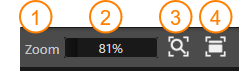
| 1 | Zoom | Click on the "**Zoom**" text to reset the State Machine diagram to a **100% zoom factor**. |
| 2 | Zoom Slider | Use this **zoom slider** to **adjusts the display magnification** of the diagram. |
| 3 | View whole layout | This function **automatically scales the view** so that all elements in the diagram fit within the display area.
|
| 4 | Switch to selected node | Centers the view on the currently selected element in the diagram. |
# Components in State Machine
A State Machine diagram is built by combining core components such as **States** and **Transitions.** Typically, a set of states are interconnected through transitions to represent the flow of logic.
The following eight types of elements can be used as components of a State Machine in the Scene Composer. These components are available in the toolbar at the top of the State Machine Editor panel and can be added to the diagram using a simple drag-and-drop action.
### Initial State
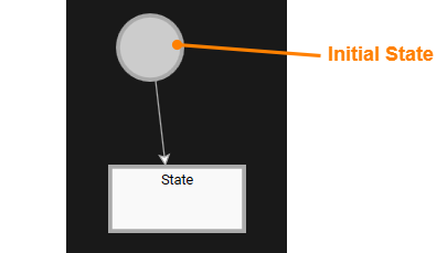
The **Initial State** is a special state that marks the starting point of the State Machine. Every State Machine contains exactly one Initial State. When the State Machine is executed, processing always begins from this Initial State.
### State
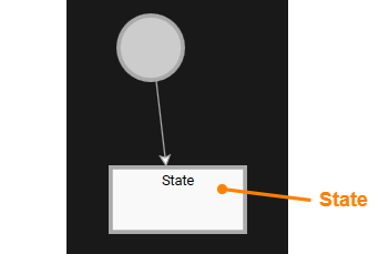
A **State** represents a specific logical condition within a State Machine. It reflects the current operation and context of the system. Specific actions can be executed when a State is entered or exited:
- **OnEntry Actions** - Executed when the State starts.
- **OnExit Actions** - Executed when the State ends.
These actions can be configured in the Properties Panel or the Fusion Editor after selecting the target State.
### Transition
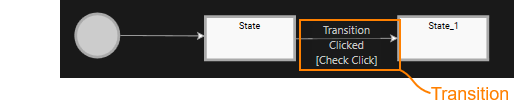
A Transition represents a connection between two States and is executed when specific conditions are met.Each transition consists of:
- **Sender** - The source that triggers the **Event**, which in turn initiates the **Transition.**
- **Event** - The event that initiates the Transition.
- **Condition** - A logical expression that must evaluate to true for the transition to occur.
- **Actions** - The operations executed when the condition is satisfied.
Transitions are evaluated in the logical order defined within the State Machine. If multiple transitions originate from the same State, you an assign priorities to determine which transition should be executed first. For more details, see [here](https://doc316en.candera.eu/link/203#bkmrk-%E9%81%B7%E7%A7%BB%E3%81%AE%E5%84%AA%E5%85%88%E9%A0%86%E4%BD%8D).
### Subchart
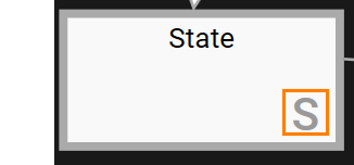
A Subchart is a structure that groups one or more **States** and **Transitions** into a single unit. In the diagram, the lower-right corner of a Subchart is marked with an “**S**” to distinguish it from a normal State.
Subcharts can be connected to other States or Subcharts, enabling the creation of flexible and modular flow structures. **Double-clicking** a Subchart opens its internal details, allowing you to view and edit its contents.
Because Subcharts can be edited independently of the main diagram, they are ideal for organizing complex logic into smaller, easy-to-understand sections.
### Entry/Exit Point
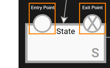
Entry Points and Exit Points are pseudo-states that enable controlled entry into and exit from a **Subchart**. They serve as clear starting and ending positions for navigating a Subchart.
- **Entry Points**: Allow the Subchart to start from different positions based on specific conditions. Multiple Entry Points can be defined to handle various scenarios.
- **Exit Points**: Provide controlled exits from the Subchart. Multiple Exit points can be configured to return to different states depending on the conditions
Using Entry and Exit Points enables the creation of modular and condition-driven flows within complex State Machine diagrams.
#### Example of Subchart Configuration Using Entry/Exit Point
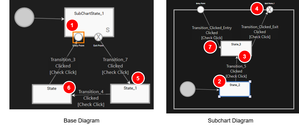
The following example shows a simple configuration that incorporates a **Subchart** along with **Entry Points** and **Exit Points**.
In the figure above, the Subchart named "SubChartState\_1" is placed within the State Machine diagram.
1. The state machine starts at the Initial State in the base diagram (see left figure above). From there it transitions into the Subchart state "SubChartState\_1".
2. Inside the Subchart (see right figure above), the flow begins at the SubChart's Initial State and proceeds to State\_2.
3. A mouse click triggers "Transition\_5", moving the flow to State\_3 within the Subchart.
4. Another mouse click initiates a transition via the Subchart's Exit Point.
5. And returns to the base diagram at State\_1.
6. A subsequent mouse click transitions to the base diagram's "State".
7. With yet another mouse click, "Transition\_3" in the base diagram is triggered, leading to the Entry Point of SubChartState\_1 (orange frame in the left diagram). This re-enters the Subchart via the Entry Point and returns to State\_3 inside the Subchart..
### History State
A **History State** is a special State that can be placed inside a **Subchart**. Its purpose is to remember the last active state within the Subchart. When the flow transitions back into the Subchart, processing resumes from the state that was active immediately before exiting, rather than starting from the Subchart's Initial State.
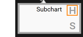
Subcharts that contain a History State are marked with an "**H**" in the top-right corner of the Subchart in the diagram.
#### Example of History State Configuration
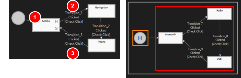
The following example demonstrates a simple configuration where a History State is placed inside a Subchart. This setup allows the State Machine to resume from the last active state within the Subchart when re-entering, rather than starting from the Initial State.
In the figure above, the State Machine diagram contains a Subchart "Media". The Subchart itself includes a History State instead of an Initial State.
- The State Machine starts at the Initial State in the base diagram and transitions to the Subchart "Media" (see the left diagram above).
- Upon entering the Subchart, it first passes through the History State (orange boxed area) and then enters the **State loop** (red boxed area), starting with the "Bluetooth" state.
- The state machine remains in this Subchart as long as transitions between **Bluetooth**, **Radio**, and **USB** are triggered.
- When Transition\_1 (marked as 2 in the figure) is triggered, the Subchart exits.
- At this point, the **History State** records the last active state within the Subchart before the exit.
- If the State Machine transitions back to the Subchart "Media" via Transition\_3 (marked as 3 in the figure), it re-enters the Subchart.
- Thanks to the History State, the Subchart resumes from the last active state (e.g. Bluetooth, Radio or USB) instead of starting from the Initial State.
When exiting the **Media** state and transitioning to the **Navigation** state, the system executes not only the **OnExit** actions of the **Media** state, but also the **OnExit** actions of the last active Media device state (e.g. **Bluetooth, USB** or **Radio**).
When entering the **Media** state, the system executes both levels of OnEntry actions: the Media state's OnEntry actions and the OnEntry actions of the stored most recently selected Media device state (e.g. **Bluetooth**, **USB** or **Radio**).
For an example implementation that demonstrates the use of a **History State** within a Subchart, see [State Machine Solution.](https://doc316en.candera.eu/books/best-practice/chapter/state-machine-solution)
### Note
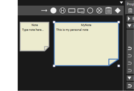
In the **State Machine Editor**, you can add **Notes** to the diagram to provide additional information, such as TODOs, caveats, implementation details or design considerations. Notes help improve clarity and make complex diagrams easier to understand and maintain.
### Choice
A **Choice** element allows you to branch **Transitions**, enabling the State Machine to enter a specific state based on the evaluation of multiple conditions. This feature simplifies the design and maintenance of complex logic where a set of conditions must be checked to determine the next state.
#### Example of Choice Usage
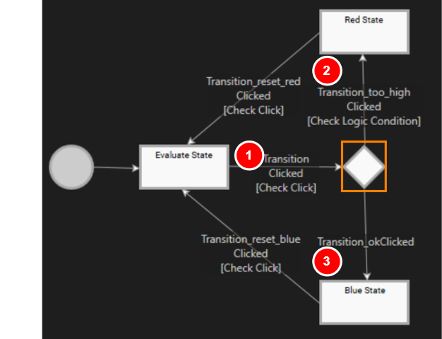
In the State Machine diagram below, the transition begins at the Initial State and proceeds to the **Evaluate State**.
When "Transition" (marked as 1 in the above figure) is triggered by a mouse click, the State Machine moves to the **Choice** element (orange-framed section in the figure). At this point, the transition branches based on the evaluated conditions:
- "**Transition\_too\_high**": The processed value is checked against a specific threshold.
- **If the condition is met** (value exceeds the threshold): The State Machine transition to "**Red State**" (marked as 2 in the figure).
- "**Transition\_okClicked**":
- **If the condition is not met** (value is below the threshold): Transition\_okClicked is executed, and the State Machine moves to "**Blue State**" (marked as 3 in the figure).
The priority of an **Exit Transition** connected to a **Choice** element is the same as the [normal Transition priority change procedure](https://doc316en.candera.eu/link/203#bkmrk-%E9%81%B7%E7%A7%BB%E3%81%AE%E5%84%AA%E5%85%88%E9%A0%86%E4%BD%8D).
By utilizing **Choice** elements, multiple conditions can be clearly organized within the State Machine, making the branching structure easy to visualize. This makes it possible to design complex logic in a simple manner.
### ViewState
ViewState is a specialized State used to control whether a specific **[View](https://doc316en.candera.eu/books/view-editor/page/view)** is displayed or hidden during the State Machine flow. It is linked to a corresponding View defined in the [**View Definition Editor**](https://doc316en.candera.eu/books/view-editor/page/view-definition-editor).
There are two ways to created a ViewState:
1. **Dragging a View from Solution Explorer**
- Drag a View directly from the Solution Explorer and drop it onto the State Machine Editor diagram
- A corresponding ViewState is created automatically.
2. **Using the State Machine Editor toolbar**
- Select the ViewState element from the toolbar and place it onto the diagram.
- In the Properties panel, configure the ViewState's view.
When configuring a State Machine that switches from displaying one scenario to displaying another, the configuration effort is significantly reduced when using **ViewStates** instead of **States** and **TransitionRequests**.
Please also see [Jump To View Action.](https://doc316en.candera.eu/books/controls-and-behaviors/page/action-behaviors)
# Basic Operation
### State Machine in the Menu Bar
The **State Machine** menu in the menu bar, offers the following options.
| New State Machine... | Select this option to create a new State Machine. For details, refer to [How to Create a new State Machine](#bkmrk-%E3%82%B9%E3%83%86%E3%83%BC%E3%83%88%E3%83%9E%E3%82%B7%E3%83%B3%E3%81%AE%E6%96%B0%E8%A6%8F%E4%BD%9C%E6%88%90%E6%96%B9%E6%B3%95). |
| Attach... | Connect to the currently running CGI Panel.
After selecting this option, the **Attach to application** dialog will be displayed. Enter the IP address and port number of the target CGI Panel. This option is also used when utilizing the Debugger panel. For more details, please refer to [State Machine Debugger](https://doc316en.candera.eu/books/state-machine/page/debugger). |
| Validate Active State Machine | Select this option to perform validation on the currently active State Machine. |
### How to Create a New State Machine
There are two ways to create a new State Machine:
#### 1. Create State Machine in Solution Explorer
1. In the **Solution Explorer**, right click any folder (e.g. Solution).
- The **context menu** will open.
2. From this menu, select **Add** > **New Item...**
- The **Add New Item** dialog appears.
3. In the list on the left, select **StateMachine**, then configure the settings displayed on the right side of the dialog. Confirm your configuration by clicking **OK**.
- A new **StateMachine** item will be created in the selected location within the **Solution Explorer**.
#### 2. Create State Machine via the Menu
1. From the menu bar, select **State Machine** > **New State Machine...** .
- The **Add New State Machine** dialog appears.
2. Configure the available settings (e.g. location, name) in the dialog and click **OK**.
- A new **State Machine** item will be created in the selected location within the **Solution Explorer**.
**Multiple State Machines** can be created using the [Multiple Clones ](https://doc316en.candera.eu/books/scene-design/page/manage-nodes#bkmrk-clone%2C-delete%2C-renam)approach in the Solution Explorer.
Each **State Machine** is associated with a specific **scope** defined by its placement. For example, you can create a different State Machine for each **scene** to manage behavior according to scope.
#### Adding a State Machine to a Node (State Machine behavior)
When a State Machine is created for a node in the scene tree, it is automatically associated with that node. Once the association is complete, the State Machine can be configured using the State Machine Editor.
1. In the Scene Tree panel, right click any node of the scene tree.
- The context menu will open.
2. From this menu, select **Add State Machine...**
- The **Add New State Machine** dialog appears.
3. Configure the settings in the dialog and click **OK.**
- A new **State Machine** item will be created in the selected location within the **Solution Explorer**.
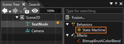
- Additionally, this State Machine appears in the **extra scene tree** of the associated node (see figure below), as it functions as a **State Machine behavior**.
A State Machine created like this is automatically connected as a [State Machine behavior](https://doc316en.candera.eu/books/controls-and-behaviors/page/state-machine-behaviors) in the extra scene tree of the target node. This connection allows the State Machine to receive all events generated by the target node and trigger the appropriate action based on the predefined logic. This mechanism allows for more intuitive and efficient control by linking visual elements (nodes) with behavioral logic (State Machines).
### StateMachine Properties
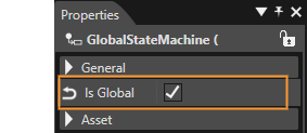
Each State Machine can operate either as a **global** or a **local** State Machine. When you create a new, empty Scene Composer solution, a **global State Machine** is included by default. Any **newly created State Machine** is a **local State Machine** unless you explicitly enable the **IsGlobal** property (see figure below).
Multiple GlobalStateMachines can be set up as needed. This capability allows you to manage complex, solution-wide behavior by coordinating logic that applies across all scenes.
#### Global State Machine
A **Global State Machine** is a State Machine that applies to the **entire solution**. It is active across **all scenes** and begins operating automatically when the solution starts.
- If an event occurs on any node in the Scene Tree and is **not handled by a Local State Machine**, the event is forwarded to the **Global State** Machine, which can then process it according to its defined logic.
- You can configure **multiple Global State Machines**. Each of them can receive and handle events that were not processed by any Local State Machines, enabling flexible, solution-wide control and coordination of behavior.
#### Local State Machine
A **Local State Machine** is a State Machine that is explicitly associated with a specific **node** (an element within the application).
- Local State Machines receive **all events** generated by the node they are connected to.
- You can configure **multiple Local State Machines** for the same node. If an event is **not handled** by any of these Local State Machines, it is passed on to other Local State Machines and ultimately to any **Global State Machines**.
A newly created State Machine is a **Local State Machine by default**. To convert it into a **Global State Machine**, enable the **Is Global** option as described above.
### Priority of Transitions
When multiple Transitions originate from the same State, their **priority** can be configured in two ways. The State Machine evaluates Transition conditions **in order of priority**, and the first Transition whose condition evaluates to *true* is executed.
This mechanism is particularly useful when multiple Transitions share the **same triggering condition**, as it allows you to clearly define which Transition should take precedence and ensures predictable, well-controlled behavior.
#### Settings on the State/Transition view
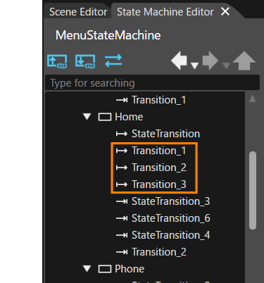
Transitions are displayed in a **tree view** in the upper-left corner of the **State Machine Editor**. In this tree view, Transitions are ordered **from top to bottom according to their priority** - the Transition at the top has the highest priority, and the one at the bottom has the lowest.
You can easily change the priority by **dragging and dropping** Transitions within the tree view. For example, in the configuration highlighted in orange in the figure below, **Transition\_1** has the highest priority and **Transition\_3** has the lowest priority.
#### Settings on the Properties panel
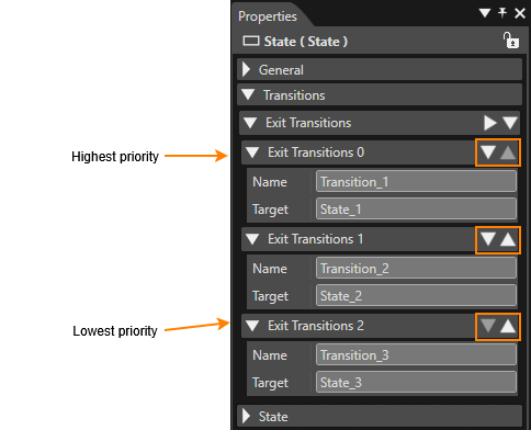
Transitions pointing away from a certain State are called exit transitions. All exit transitions for a certain State are displayed in the properties panel in the **Transitions** > **Exit Transitions** section. In this list, Transitions are displayed **from the top to bottom in order of priority**, with the highest-priority Transition at the top.
You can easily adjust the priority using the **Move Item Up** and **Move Item Down** icons (orange-highlighted area in the figure).
### Add an Element
Each element available in the **State Machine Editor** top toolbar can be added to the diagram using **drag-and-drop**. When placing elements, observe the following restrictions:
- Only **one Initial State** can be placed in each State Machine.
- **History States**, **Entry Points**, and **Exit Points** can be placed **only inside a Subchart**.
These constraints ensure correct State Machine structure and prevent invalid configurations.
### Add a Transition
Interconnecting States with Transitions is a two-step process:
1. **Drag and Drop a Transition**
Drag a **Transition** from the top toolbar and drop it onto the **source State**, releasing the mouse button.
2. **Select the destination State**
Move the mouse towards the **destination State**. As you do so, a Transition arrow will stretch from the source State to the mouse cursor. Drag the arrow onto to the destination State and complete the connection with a mouse click.
This procedure establishes a Transition linking the selected source State to the chosen destination State.
### Transition Inflection Points
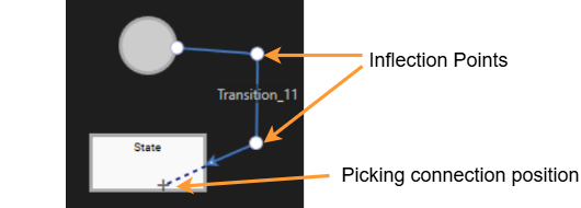
You can add an Inflection Point to the location you click by holding down the **Ctrl** key and clicking on the Transition in the diagram. Adding an Inflection Point allows you to adjust the shape of the Transition line, giving you more control over how the Transition is visually routed within the diagram.
### Changing Element Size
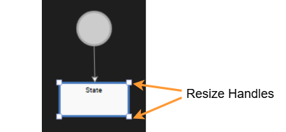
**State**, **History State**, **Subchart** and **Note** elements can be resized freely within the diagram. After placing the element on the canvas, you can adjust its size it by dragging the **resize handles** with the mouse.
### Deleting an element
Elements placed on the State Machine Editor diagram can be deleted in the following ways:
- **Delete from the diagram
**Select the element on the diagram and press the **Delete** key on your keyboard.
- **Delete from the editor tree (State/Transition view)** In the **editor tree**, select the element you want to remove, then either right-click and choose **Delete** from the context menu or press the **Delete** key on your keyboard.
### Subchart
In addition to dragging and dropping a **Subchart** from the top toolbar onto a diagram, you can also create a Subchart by **converting it from an existing State**.
##### Converting to Subchart
A State can be converted to a Subchart by selecting **Convert to Subchart** from the context menu after selecting the State. The original State name is retained after the conversion, but it can be renamed as needed.
### Display and Placement of Entry and Exit Points
**Entry Points** and **Exit Points** can be positioned along the **edges of the Subchart**, clearly defining the flow in and out of the Subchart. When viewing the Subchart on a diagram, these points are also visually indicated, making it easier to grasp the overall flow.
Entry and Exit Points can be **freely rearranged** along the subchart's edge. Thoughtful placement of these points improves readability, enhances structural clarity, and contributes to a more intuitive State Machine design.
### Note
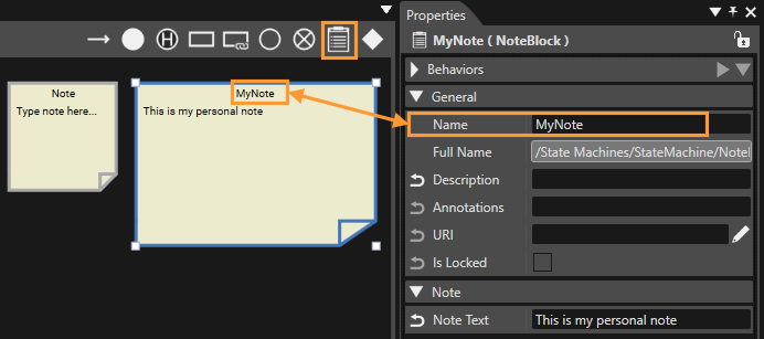
You can add Note to your diagrams in the State Machine Editor. To insert a Note, drag the **Note** element from the State Machine Editor toolbar and drop it onto the diagram.
Note can be **resized** in the same way as States - simply drag the **resize** handles to adjust their dimensions. The **Note titles** can be edited in the Properties panel. Clicking on a Note switches it into **text-editing mode** allowing you to modify its content directly on the diagram.
### Design Options
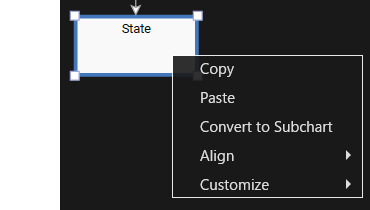
When right-clicking on a selected **State** or **Transition** on a diagram in the **State Machine Editor**, a context menu appears.
| Copy | Copies the selected elements. The copied elements can be pasted onto the diagram using the Paste operation. |
| Paste | Pastes the copied elements onto a diagram. Note that Transitions are only pasted if both the source and destination States are included in the copied selection. |
| Convert to Subchart | Convert the selected State to a Subchart. See [here](#bkmrk-state-subchart) for details. |
| Align | When multiple items are selected,their positions on the diagram can be aligned for consistent layout and improved readability.
Available alignment options include: left, center, right, top, middle, bottom. Additionally, **Distribute Horizontal** and **Distribute Vertical** can be used to evenly space selected items, helping keep the diagram clean and well-organized.
|
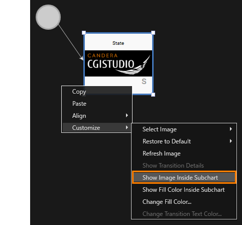
| Customize | Decorate the selected State by applying an **image** or filling it with a custom color. For details, please refer to [Changing Styles](#bkmrk-changing_styles).
|
#### Changing Styles
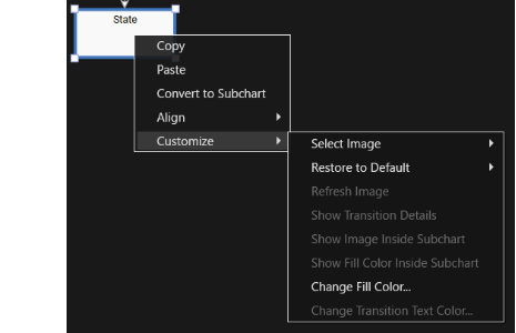
The Scene Composer State Machine Editor allows you to customize States and Transitions using background images and color settings. Applying visual styling can improve the readability of the State Machine diagram and enhance its intuitiveness, specially in complex designs.
| From Solution Explorer... | The **Choose Item** dialog opens, allowing you to select any image of the Scene Composer solution. Note that you can only select images that have been imported into the solution beforehand. |
| From Local File... | Opens the **Windows OS Select File** dialog, allowing you to choose a local image file from your file system. |
##### Restore to Defaults
Restores the **default settings** for elements that support design customization options. You can choose which defaults to restore by selecting an option from the available menu.
| All | Resets all design settings for the selected element back to their default values. |
| Image | Restores only the element's background to its default setting. |
| Fill Color | Restores only the element's fill color to its default setting. |
| Transition Text Color | Restores only the Transition text color to its default setting.
|
| Transition Details Visibility | Restores only the Transition detail visibility settings to its default. |
| Connection Type | Restores only the Transition connection type (line type) to its default setting. (The default settings for Transition connection types can be found in [Preferences](https://doc316en.candera.eu/books/preferences/page/state-machine)).
|
##### Refresh Image
This option is only available when an image is already assigned to the target State. Reloads the image from the file or captures a new screenshot from the scene/camera.
##### Show Transition Details
When this option is enabled, the transition's name **and** details are displayed next to the transition arrow. When disabled, only the transition's name is displayed.
#####
Show Image Inside Subchart
This option is only available for a Subchart State. If this option is enabled, the image set for the State is displayed in the Subchart as background image.
#####
Show Fill Color Inside Subchart
This option is also only available for a Subchart State. If the **Change Fill Color** option (described below) is enabled for the Subchart State, turning on this option applies the State's fill color to the Subchart's background.
##### Change Fill Color
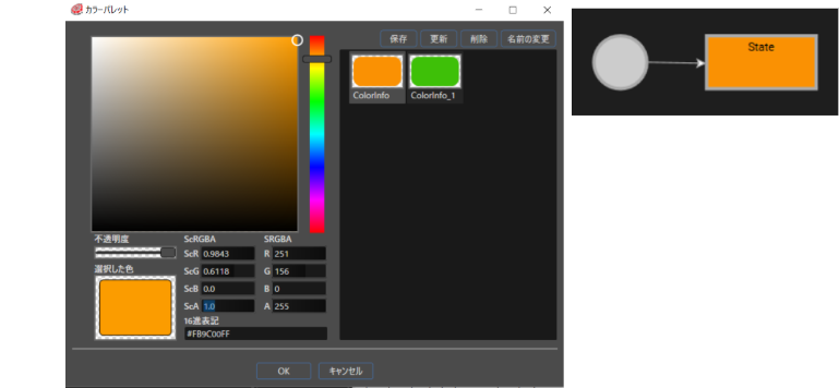
Allows you to change the background color of the State. Selecting this option opens the **Color Palette** dialog, where you can choose the desired color and confirm with **OK**.
##### Change Transition Text Color
Allows you to change the text color of a Transition's text description. You can change the name text color setting for Transition. Selecting this option opens the **Color Palette** dialog, where you can choose the desired color and confirm with **OK**.
### Using Shortcut Keys
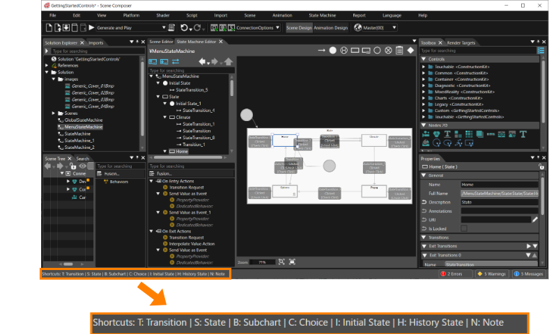
The **State Machine Editor** supports shortcut keys to help you perform some operations more efficiently allowing quick addition and manipulation of elements.
##### Operation Procedure with Shortcut Keys
1. **Mouse over**
Move the mouse cursor to any location or element on the diagram.
2. **Check Available Shortcuts**
All available shortcut keys are displayed in the **lower-left corner** of the Scene Composer window.
3. **Enter a Shortcut Key**
Press one of the displayed shortcut keys on the keyboard to execute the corresponding action.
In the example below, **Transition, State, Subchart, Choice, Initial State, History State**, and **Note** can all be added using shortcut keys.
### Diagram Bird's Eye Function
You can display the **Diagram Bird's Eye** panel by selecting **View > State Machine > Diagram Bird's Eye** from the menu bar.The panel provides an overview of the entire State Machine Editor workspace, allowing you to quickly navigate large or complex diagrams.
For details on viewing and operating this panel, see [Diagram Bird's Eye](https://doc316en.candera.eu/books/solution-handling/page/diagram-birds-eye).
### Undo and Redo
The State Machine Editor supports "**Undo and Redo**" operations, enabling safe and flexible editing of State Machine diagrams.
Please note that **adding, deleting** or **editing** of a Transition's **Inflection Point** is not supported by the Undo and Redo feature.
For more information, see [Undo and Redo Operations](https://doc316en.candera.eu/link/32#bkmrk-page-title).
# Debugger
A dedicated debugger is provided as an important tool to complement the state machine modeling process. This section describes its usage.
#### How to Start the Debugger Panel
Open the debugger panel by selecting **View > State Machine > State Machine Debugger** from the menu bar.
#### How to Use
After opening the debugger panel, integrate it with the CGI Panel using one of the following methods and perform debugging operations.
1. Start the Player Panel by clicking the **Play selected scenario** button on the toolbar. This launches the CGI Panel.
2. From the menu bar, select **State Machine > Attach...** to connect to a CGI Panel that is already running.
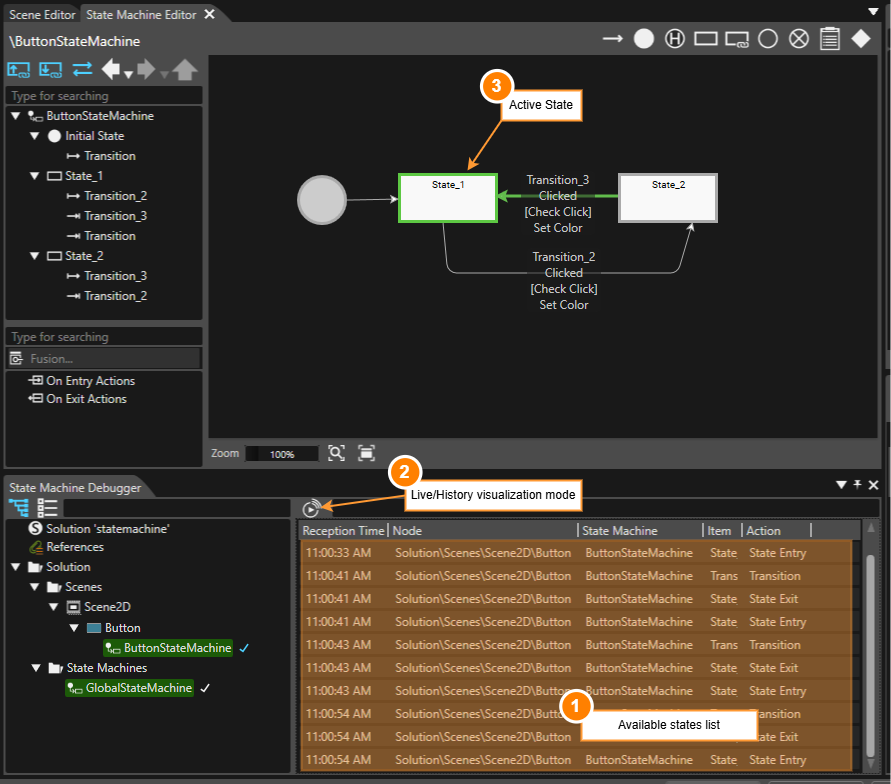
#### Debugger Panel Functionality
The figure above shows the debugger panel positioned directly below the State Machine Editor panel. See below for a description corresponding to the numbers in the above figure.
| 1 | Available states list | Actions are logged and listed together with a their associated Node and State or Transition. |
| 2 | Live/History visualization mode | Use this button to switch between live (real-time) and history visualization mode. |
| 3 | Active State | When the CGI Panel is running and the debugger is attached, the active state of the current State Machine is indicated in the diagram. |
This functionality makes the following tasks easier:
- Tracking Transitions
- Verifying the execution order of actions and transitions.
- Debugging State Machine logic
# Example
The following book provides examples of how to use state machines:
[Best Practices > State Machine Solutions](https://doc316en.candera.eu/books/best-practice/chapter/state-machine-solution)
This book outlines best practices for creating IVI solutions using state machines and includes detailed operating procedures. It is organized into five parts according to purpose, and it is recommended to work through them sequentially, beginning with "Part 1". The subsequent parts are especially useful as references for practical configuration procedures.
| [Part 1: Prepare Scenes](https://doc316en.candera.eu/books/best-practice/page/part-1-prepare-scenes) | Provides procedures for **creating scenes** that are common to the **best practices of State Machines**. You must complete the steps in this part before proceeding to any subsequent parts. |
| [Part 2: Configuring State Machine](https://doc316en.candera.eu/books/best-practice/page/part-2-configuring-state-machine) | Covers the basic operations required to build State Machines, including Global State Machine settings, **OnEntry** and **OnExit** actions for States, and configuration options for each Transition. |
| [Part 3: Subchart and History State](https://doc316en.candera.eu/books/best-practice/page/part-3-subchart-and-history-state) | Explains how to use and configure **Subchart** and **History States.** |