# MVG Nodes

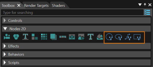
MVG Nodes can be created in CGI Studio SceneComposer via the Toolbox. Simply drag and drop the desired MVG Node into the Scene Editor or Scene Tree Panel.

The following MVG Nodes are available:

- MVG Arc Node
- MVG Ellipse Node
- MVG Path Node
- MVG Rect Node

<div drawio-diagram="6279"><img src="https://doc316en.candera.eu/uploads/images/drawio/2024-06/drawing-5-1718378815.png" alt=""/></div>

<p class="callout info">You can see an application of MVG nodes in Scene Composer's **2D Basic sample**.</p>

#### Configure MVG Nodes

An MVG node is a RenderNode2D and therefore it has the same properties that can be configured in the properties panel:

- General. Name, Full Name, Description...
- 2D Render Node: Render Order Rank...
- Transformation: Position, Pivot Point, Pivot Offset...
- Asset: Id, Symbolic Name...
- Item: Scope Mask, Alpha Value...
- Layout: Vertical Alignment, Horizontal Alignment, Size...

Further details like the visual appearance of MVG nodes can be configured in the node's effect. Each type of MVG node has its appropriate effect:

<table border="1" id="bkmrk-mvg-node-mvg-brush-m" style="border-collapse: collapse; width: 41.8519%; height: 157px;"><colgroup><col style="width: 50.0412%;"></col><col style="width: 50.0412%;"></col></colgroup><tbody><tr><td>**MVG Node**  
</td><td>**MVG Brush**  
</td></tr><tr><td>MVG Arc Node </td><td>MVGArcBrush</td></tr><tr><td>MVG Ellipse Node </td><td>MVGEllipseBrush</td></tr><tr><td>MVG Path Node </td><td>MVGPathBrush</td></tr><tr><td>MVG Rect Node </td><td>MVGRectBrush</td></tr></tbody></table>

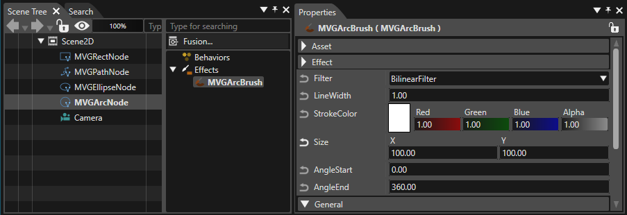
Select the MVG Node in the Scene Tree and select the attached MVG effect in the right side of the Scene Tree to view its properties in the properties panel.

<div drawio-diagram="7598"><img src="https://doc316en.candera.eu/uploads/images/drawio/2024-12/drawing-5-1733485928.png" alt=""/></div>

#### MVG Arc Node - MVGArcBrush

Can be used to render an arc.

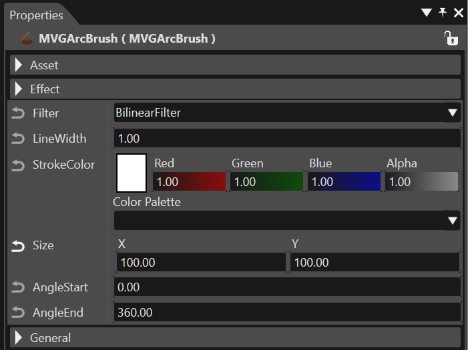
The properties of the MVG Arc Node are those of a regular RenderNode2D. For the attached effect MVGArcBrush, the following properties can be configured:

<div drawio-diagram="6282"><img src="https://doc316en.candera.eu/uploads/images/drawio/2024-06/drawing-5-1718379101.png" alt=""/></div>

<table border="1" id="bkmrk-filter-filter-for-re" style="border-collapse: collapse; width: 100%;"><colgroup><col style="width: 12.7324%;"></col><col style="width: 87.2244%;"></col></colgroup><tbody><tr><td>Filter  
</td><td>Filter for rendering (choose between BilinearFilter and NearestFilter).</td></tr><tr><td>Line Width  
</td><td>Width of the rendered line in pixels.</td></tr><tr><td>Stroke Color  
</td><td>Color of the rendered line.</td></tr><tr><td>Size  
</td><td>Vertical (X) and horizontal (Y) size of the arc to be rendered.</td></tr><tr><td>Angle Start  
</td><td>The angle of the arc's starting point.</td></tr><tr><td>Angle End  
</td><td>The angle of the arc's end point.</td></tr></tbody></table>

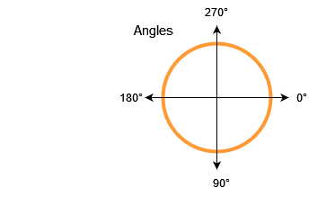
<p class="callout info">The arcs starting and end point have to be entered in degrees. Please also see the sketch below.</p>

<div drawio-diagram="4867"><img src="https://doc316en.candera.eu/uploads/images/drawio/2023-11/drawing-4-1700541631.png" alt=""/></div>

#### MVG Ellipse Node - MVGEllipseBrush

Can be used to render an ellipse.

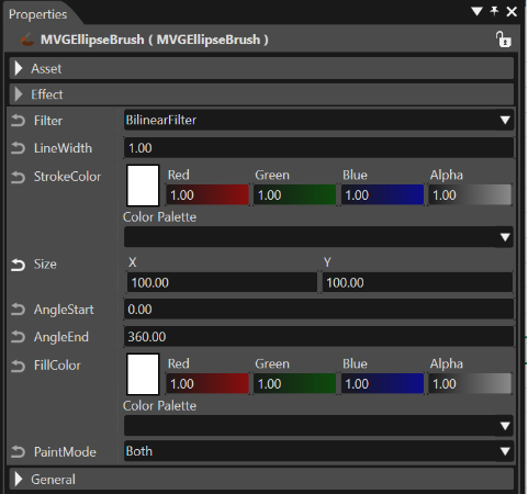
The properties of the MVG Ellipse Node are those of a regular RenderNode2dD. For the attached effect MVGEllipseBrush, the following properties can be configured:

<div drawio-diagram="6283"><img src="https://doc316en.candera.eu/uploads/images/drawio/2024-06/drawing-5-1718379150.png" alt=""/></div>

<table border="1" id="bkmrk-filter-filter-for-re-1" style="border-collapse: collapse; width: 100%;"><colgroup><col style="width: 12.7324%;"></col><col style="width: 87.2244%;"></col></colgroup><tbody><tr><td>Filter  
</td><td>Filter for rendering (choose between BilinearFilter and NearestFilter).</td></tr><tr><td>Line Width  
</td><td>Width of the rendered line in pixels.</td></tr><tr><td>Stroke Color  
</td><td>Color of the rendered line.</td></tr><tr><td>Size  
</td><td>Vertical (X) and horizontal (Y) size of the arc to be rendered.</td></tr><tr><td>Angle Start  
</td><td>The angle of the ellipse's starting point.</td></tr><tr><td>Angle End  
</td><td>The angle of the ellipse's end point.</td></tr><tr><td>FillColor  
</td><td>Fill color of the ellipse.</td></tr><tr><td>PaintMode  
</td><td>Configures if the ellipse will be rendered with outline *and* filling or with either of those (choose between Both, Fill and Stroke).</td></tr></tbody></table>

#### MVG Path Node - MVGPathBrush

Can be used to render paths with a combination of instructions.

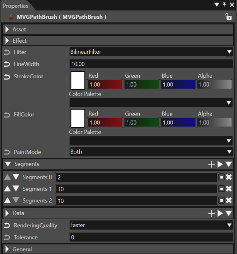
The properties of the MVG Path Node are those of a regular RenderNode2dD. For the attached effect MVGPathBrush, the following properties can be configured:

<div drawio-diagram="6284"><img src="https://doc316en.candera.eu/uploads/images/drawio/2024-06/drawing-5-1718379295.png" alt=""/></div>

<table border="1" id="bkmrk-filter-filter-for-re-2" style="border-collapse: collapse; width: 100%;"><colgroup><col style="width: 14.8256%;"></col><col style="width: 85.1332%;"></col></colgroup><tbody><tr><td>Filter  
</td><td>Filter for rendering (choose between BilinearFilter and NearestFilter).</td></tr><tr><td>LineWidth  
</td><td>Width of the rendered line in pixels.</td></tr><tr><td>Stroke Color  
</td><td>Color of the rendered line.</td></tr><tr><td>FillColor  
</td><td>Fill color of the path.</td></tr><tr><td>PaintMode  
</td><td>Configures if the path will be rendered with outline *and* filling or with either of those (choose between Both, Fill and Stroke).</td></tr><tr><td>Segments</td><td>Defines segments.

<table border="1" style="width: 100.147%;"><tbody><tr><td class="align-center" style="width: 7.60042%;">Input value</td><td class="align-center" style="width: 17.8801%;">VGPathSegment</td><td class="align-center" style="width: 10.2862%;">number of Data</td><td class="align-center" style="width: 64.231%;">Description</td></tr><tr><td class="align-center" style="width: 7.60042%;">0</td><td style="width: 17.8801%;">ClosePath</td><td class="align-center" style="width: 10.2862%;">0</td><td style="width: 64.231%;">Closing a path by connecting a final coordinate to a start coordinate. Therefore, the required number of Data is 0.

</td></tr><tr><td class="align-center" style="width: 7.60042%;">2</td><td style="width: 17.8801%;">MoveTo</td><td class="align-center" style="width: 10.2862%;">2</td><td style="width: 64.231%;">Specify coordinates of a path starting point. Therefore, the required number of Data is two (x0, y0).

</td></tr><tr><td class="align-center" style="width: 7.60042%;">4</td><td style="width: 17.8801%;">LineTo</td><td class="align-center" style="width: 10.2862%;">2</td><td style="width: 64.231%;">Draws a straight line. Specify an end point coordinates. Therefore, the required number of Data is two (x0, y0). A straight line is drawn from a coordinates specified in the previous Segment to a coordinates specified in this Segment.

</td></tr><tr><td class="align-center" style="width: 7.60042%;">6</td><td style="width: 17.8801%;">HLineTo</td><td class="align-center" style="width: 10.2862%;">1</td><td style="width: 64.231%;">Draws a horizontal line. The required number of Data is only one (x0).

</td></tr><tr><td class="align-center" style="width: 7.60042%;">8</td><td style="width: 17.8801%;">VLineTo</td><td class="align-center" style="width: 10.2862%;">1</td><td style="width: 64.231%;">Draws a vertical line. The required number of Data is only one (y0).

</td></tr><tr><td class="align-center" style="width: 7.60042%;">10</td><td style="width: 17.8801%;">QuadTo</td><td class="align-center" style="width: 10.2862%;">4</td><td style="width: 64.231%;">Draws a quadratic Bezier curve. Specify a coordinates of a control point and an end point. Therefore, the required number of Data is 4 (x0, y0, x1, y1). Please refer the below image as an example.

</td></tr><tr><td class="align-center" style="width: 7.60042%;">12</td><td style="width: 17.8801%;">CubicTo</td><td class="align-center" style="width: 10.2862%;">6</td><td style="width: 64.231%;">Draws a cubic Bezier curve. Specify coordinates of two control points and an end point. Therefore, the required number of Data is 6 (x0, y0, x1, y1, x2, y2). Please refer the below image as an example.

</td></tr></tbody></table>

</td></tr><tr><td>Data</td><td>Defines Data according to the specified Segment.</td></tr></tbody></table>

#### MVG Rect Node - MVGRectBrush

Can be used to render a rect.

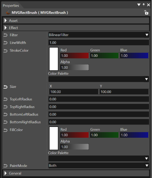
The properties of the MVG Rect Node are those of a regular RenderNode2dD. For the attached MVGRectBrush, the following properties can be configured:

<div drawio-diagram="6285"><img src="https://doc316en.candera.eu/uploads/images/drawio/2024-06/drawing-5-1718379336.png" alt=""/></div>

<table border="1" id="bkmrk-filter-filter-for-re-3" style="border-collapse: collapse; width: 100%;"><colgroup><col style="width: 17.7939%;"></col><col style="width: 82.1649%;"></col></colgroup><tbody><tr><td>Filter  
</td><td>Filter for rendering (choose between BilinearFilter and NearestFilter).</td></tr><tr><td>LineWidth  
</td><td>Width of the rendered line in pixels.</td></tr><tr><td>Stroke Color  
</td><td>Color of the rendered line.</td></tr><tr><td>Size  
</td><td>Vertical (X) and horizontal (Y) size of the arc to be rendered</td></tr><tr><td>TopLeftRadius  
</td><td>Radius of the top left corner.  
</td></tr><tr><td>TopRightRadius  
</td><td>Radius of the top right corner.</td></tr><tr><td>BottomLeftRadius  
</td><td>Radius of the bottom left corner.</td></tr><tr><td>BottomRightRadius  
</td><td>Radius of the bottom right corner.</td></tr><tr><td>FillColor  
</td><td>Fill color of the path.</td></tr><tr><td>PaintMode  
</td><td>Configures if the rectangle will be rendered with outline *and* filling or with either of those (choose between Both, Fill and Stroke).</td></tr></tbody></table>