# Configuration

#### <a class="anchor" id="bkmrk--1"></a>Description

Configuration information passed to the warping library is used to check constraints and as basis for computations.   
Following is a description of the warping configuration parameters:

#### <a class="anchor" id="bkmrk--2"></a>Reference Points

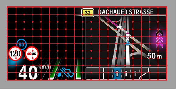
The reference points are represented by a 2D array with coordinates inside the display area to be warped. There are **NumOfRefPointsX** in horizontal direction and **NumOfRefPointsY** in vertical direction, both having values in the range 0..255. These are equally distributed over Bitmap-pixel.   
*Example*:

<div class="contents" id="bkmrk-numofrefpointsx%3A-21-"><div class="contents"><div class="textblock">- NumOfRefPointsX: 21 (0x15)
- NumOfRefPointsY: 11 (0x0B)

</div></div></div>The number of reference points used influence to output of the distorted image with regard to Bitmap size. The output image will be less jagged the higher the number of reference points are used for warping computation

#### <a class="anchor" id="bkmrk--3"></a>PixResolution

The Resolution of warping parameters determinine the warping accuracy. The final displacement of the reference points is the product of warping parameter by parameter resolution. Therefore, a warping parameter is given by the desired displacement divided by resolution.

The warping library supports the following pixel:

<div class="contents" id="bkmrk-0%3A-1%2F16-px-1%3A-1%2F8-px"><div class="contents"><div class="textblock">- 0: <sup>1</sup>/<sub>16</sub> px
- 1: <sup>1</sup>/<sub>8</sub> px
- 2: ¼ px
- 3: ½ px
- 4: 1 px
- 5: 2 px
- 6: 4 px
- 7: 8 px

</div></div></div>*Example*:   
If a texture point at (0,0) should be mapped at (10,10) the corresponding X\[0\] and Y\[0\] coordinates can be calculated by dividing the desired displacement by pixel resolution.   
For a pixel resolution of <sup>1</sup>/<sub>16</sub> px (0.0625):

```
X[0] = Xnew[0] – Xold[0] / 0.0625 = 160 (0xA0)
Y[0] = Ynew[0] –Yold[0] / 0.0625 = 160 (0xA0)
```

  
For a pixel resolution of ¼ px (0.25):

```
X[0] = Xnew[0] – Xold[0] / 0.25 = 40 (0x28)
Y[0] = Ynew[0] –Yold[0] / 0.25 = 40 (0x28)
```

#### <a class="anchor" id="bkmrk--4"></a>NumOfBitsPerParam

Represents the number of bits used for each parameter (n-bit representation = bit length of each parameter).  
The value should be in the range is 1..16.  
*Example*:

<div class="contents" id="bkmrk-if-numofbitsperparam"><div class="contents"><div class="textblock">- If NumOfBitsPerParam is 8 the warping parameters corresponding to X\[0\]Y\[0\] are represented as 0xA0 0xA0.
- If NumOfBitsPerParam is 12 the warping parameters corresponding to X\[0\]Y\[0\] are represented as 0x0A 0x00 0xA0.

</div></div></div><div class="contents" id="bkmrk-the-numofbitsperpara"><div class="contents"><div class="textblock"><dl class="note"><dd><p class="callout info">The **NumOfBitsPerParam** and **PixResolution** are represented on 8 bits, upper three bits are used for NumOfBitsPerParam and lower bit for PixResolution.</p>

</dd><dd></dd></dl></div></div></div>*Example:*:

<div class="contents" id="bkmrk-0x96--%3E-numofbitsper"><div class="contents"><div class="textblock">- 0x96 -&gt; NumOfBitsPerParam: 12, PixResolution 0 (<sup>1</sup>/<sub>16</sub> px)
- 0x98 -&gt; NumOfBitsPerParam: 12, PixResolution 2 (¼ px)

</div></div></div>#### <a class="anchor" id="bkmrk--5"></a>DisplaySizeX and DisplaySizeY

Width and height data (in pixel) of the display hardware (range: 0..65535).

*Example*:

<div class="contents" id="bkmrk-0x01-0xe0-%E2%80%93-displays"><div class="contents"><div class="textblock">- 0x01 0xE0 – DisplaySizeX – 480px width
- 0X00 0XF0- DisplaySizeY – 240 px height

</div></div></div>#### <a class="anchor" id="bkmrk--6"></a>BitmapAreaX and BitmapAreaY

Width and height data (in pixels) of source surface used as input for warp. The reference points are equally distributed over this range in x and y direction with values in the range 0..65535.

*Example*:

<div class="contents" id="bkmrk-0x01-0x98-%E2%80%93-bitmapar"><div class="contents"><div class="textblock">- 0x01 0x98 – BitmapAreaX – 408px width
- 0X00 0XBE- BitmapAreaY– 190 px height

</div></div></div><div class="contents" id="bkmrk-condition%3A%C2%A0-%C2%A0bitmapa"><div class="contents"><div class="contents"><div class="textblock"><dl class="note"><dd><p class="callout info">Condition:  
 BitmapAreaX≤ DisplaySizeX  
 BitmapAreaY≤DisplaySizeY</p>

</dd></dl></div></div></div></div>#### <a class="anchor" id="bkmrk--7"></a>BitmapAreaCenter

The Bitmap Area Center Point describes the center point of the image area used by ABK.

#### <a class="anchor" id="bkmrk--8"></a>BitmapAreaShift

The Bitmap Area Shift describes the connection vector between the origin of the bitmap coordinate system (0,0) and the center point of the bitmap area - i.e. the Bitmap Area Center Point.

#### <a class="anchor" id="bkmrk--9"></a>BitmapAreaShiftX and BitmapAreaShiftY

Shift values of bitmap area center point in horizontal and vertical direction (range 0..65535).

<div class="contents" id="bkmrk-%E2%80%9D0%E2%80%9D-bitmapareashiftx"><div class="contents"><div class="textblock">- ”0” BitmapAreaShiftX means the application window starts at the left edge on the display.
- ”0” BitmapAreaShiftY means the application window starts at the upper edge on the display.

</div></div></div>*Example*:

<div class="contents" id="bkmrk-0x00-0xcc-%E2%80%93-bitmapsh"><div class="contents"><div class="textblock">- 0x00 0xCC – BitmapShiftAreaX – 204px
- 0X00 0X5F- BitmapShiftAreaY– 95 px

</div></div></div><div class="contents" id="bkmrk-condition%3A%C2%A0-%C2%A0%28bitmap"><div class="contents"><div class="contents"><div class="textblock"><dl class="note"><dd><p class="callout info">Condition:  
 (BitmapAreaY/2+BitmapAreaShiftY≤DisplaySizeY) AND (BitmapAreaY/2– BitmapAreaShiftY ≥0  
 (BitmapAreaX/2+BitmapAreaShiftX≤DisplaySizeX) AND (BitmapAreaX/2– BitmapAreaShiftX ≥0</p>

</dd></dl></div></div></div></div>#### <a class="anchor" id="bkmrk--10"></a>IlluminatedDisplayAreaX and IlluminatedDisplayAreaY

Width and height data (in pixel) for illuminated area. This represents the region in which the warped surface will be rendered. If the source surface size extends beyond the IlluminatedDisplayArea it will be scaled down with regards to display size.

*Example*:

<div class="contents" id="bkmrk-0x01-0xe0-%E2%80%93-illumina"><div class="contents"><div class="textblock">- 0x01 0xE0 – IlluminatedDisplayAreaX – 480px width
- 0X00 0XF0- IlluminatedDisplayAreaY– 240 px height

</div></div></div><div class="contents" id="bkmrk-condition%3A%C2%A0-%C2%A0illumin"><div class="contents"><div class="textblock"><dl class="note"><dd><p class="callout info">Condition:  
 IlluminatedDisplayAreaX ≤ DisplaySizeY   
 IlluminatedDisplayAreaY ≤ DisplaySizeY</p>

</dd></dl></div></div></div>#### <a class="anchor" id="bkmrk--11"></a>IlluminatedDisplayAreaShiftX and IlluminatedDisplayAreaShiftY

Shift values of illuminatedDisplay area center point in horizontal and vertical direction (range 0..65535).

*Example*:

<div class="contents" id="bkmrk-0x00-0xf0-%E2%80%93-bitmapsh"><div class="contents"><div class="textblock">- 0x00 0xF0 – BitmapShiftAreaX – 240px
- 0X00 0X78- BitmapShiftAreaY– 120 px

</div></div></div><div class="contents" id="bkmrk-condition%3A%C2%A0-%C2%A0%28illdis"><div class="contents"><div class="textblock"><dl class="note"><dd><p class="callout info">Condition:  
 (IllDisplayAreaX/2+IllDisplayAreaShiftX≤DisplaySizeX) AND (IllDisplayAreaX/2– IllDisplayAreaShiftX ≥0)  
 (IllDisplayAreaY/2+IllDisplayAreaShiftY≤DisplaySizeY) AND (IllDisplayAreaY/2– IllDisplayAreaShiftY ≥0)</p>

</dd></dl></div></div></div>#### <a class="anchor" id="bkmrk--12"></a>RotationValue

The rotation value is represented in grad \*100 with values in the range -18000 .. +18000. This is the default rotation value which will be applied to the warp image.

The rotation takes place around the warped center point of the bitmap area used. With an uneven number of reference points in x- and y-direction, this point coincides with the middle reference grid point, and the coordinates of the rotation axis are present. If an even number of reference grid points is used, the coordinates of the warped center point of the image are be calculated.

*Example*:

<div class="contents" id="bkmrk-0x01-0xf4-%E2%80%93-rotation"><div class="contents"><div class="textblock">- 0x01 0xF4 – RotationValue: 500/100 = 50

</div></div></div>#### <a class="anchor" id="bkmrk--13"></a>ParamSet

Set of reference point shift vectors column-ordered.

The warping parameter correspond to the shift vectors (in pixels) of warping interpolation points in warped images in comparison to reference points in non-warped images (divided by the specified resolution). To save memory space and computing time, the absolute coordinates are not saved as warping parameters, but rather only the distance from the reference points (without rotation and shifting).

#### <a class="anchor" id="bkmrk--14"></a>ParamSetLength

Length of ParamSet in bytes. This is calculated by:

```
ParamSetLength = NumRefPointsX * NumRefPointsY * 2 * NumBitsPerParam
```

#### <a class="anchor" id="bkmrk--15"></a>RotationLimit

This value represents the maximal rotation angle in grad – both positive and negative values are accepted. If the RotationLimit value is chosen such that at maxim rotation point, the image will extend beyond display size, it will be scaled down to the size that fits inside the display area when a rotation equal to RotationLimit is applied.

The *display area* comprises the whole image including the grey border.  
The *bitmap image* area is the area within the grey border. This is the area we are interested in and which should be warped.  
The reference points are evenly distributed over the bitmap image area.

<div class="contents" id="bkmrk-the-illuminated-disp"><div class="contents"><div class="textblock"><dl class="note"><dt></dt><dd><p class="callout info">The illuminated display area is the part of the display, which is backlit and projected to the windshield.</p>

</dd></dl><div drawio-diagram="1543"><img src="https://doc316en.candera.eu/uploads/images/drawio/2023-02/drawing-4-1676538201.png" alt=""/></div>

  
</div></div></div>#### <a class="anchor" id="bkmrk--17"></a>Reference Point Shift Vectors

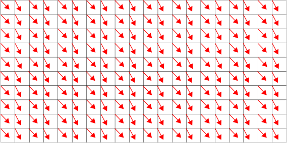
The warping parameters are based on reference point. These points are mapped by a 2D array containing coordinates inside the display area to be warped. For ++-each reference point, a shift vector is stored by the application. Every shift vector determines the amount of distortion to be applied to the corresponding point in x- and y-direction. Figure 2 shows a reference point grid with corresponding shift vectors.

To preserve memory, the shift vectors are stored in a compressed format. The format is determined by configuration information passed to warping library (number of bits used, value resolution) and is used by warping library to de- and encode shift vectors. The decoded shift vectors are cached in the warping library.

<div drawio-diagram="1544"><img src="https://doc316en.candera.eu/uploads/images/drawio/2023-02/drawing-4-1676538319.png" alt=""/></div>

<div class="contents" id="bkmrk--0"><div class="contents"><div class="textblock">  
</div></div></div>#### <a class="anchor" id="bkmrk--19"></a>Warp Matrix

The warp matrix is computed by the warping library. It is a 2-dimensional matrix. Each point corresponds to a reference point. The value of each point is the vector-addition of the reference point and corresponding shift vector. All values of the warp matrix are normalized to the range \[0..1\].

#### <a class="anchor" id="bkmrk--20"></a>Warp Image Bounds

Warp image bounds can be computed by the warping library. Warp image bounds comprise upper left corner point of the bitmap image area, its width, and height (normalized to the range \[0..1\]). They are used to specify to [Candera](http://dev.doc.cgistudio.at/APILINK/namespace_candera.html "[DataBinding_RefTypeSample]") which part of the rendered image shall be mapped to the warping mesh.