Fusion
General Overview
Functional Overview
Fusion is an editor that seamlessly combines the behavior tree and the properties panel in a powerful, yet intuitive interface.
- The behavior tree is presented as a clear, well-structured diagram for easy visualization. The behavior tree remains accessible through the extra scene tree, located on the right side of the scene tree panel.
- Node properties can be edited directly within the Fusion diagram or, alternatively, through the properties panel.
This integrated approach provides flexibility and enhances the efficiency of managing behaviors and properties in your scene.
For more information on using behaviors, see Behaviors.
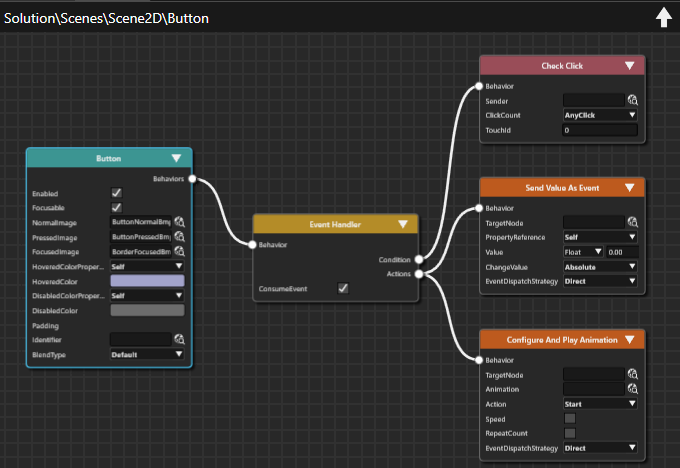
Benefits of using Fusion Editor
- Clear Visualization
Fusion Nodes that compose increasingly complex HMI elements are presented in a clear, consolidated view, making it ideal for presentations and design reviews. - Comprehensive Information
All relevant details are visible in one place, significantly reducing man-hours required for reviews and analysis - Seamless Integration
Fusion diagrams can be incorporated into solution reports, supporting the creation of detailed design documents.
Main features
- Visual Management
Provides a graphical interface for managing Fusion Nodes and their interactions within the scene - Editor Operations
Includes essential functions such as automatic alignment, magnification adjustment, zoom in/zoom out and Undo/Redo. - Color-Coded Display
Each Fusion Node is visually distinguished through color coding for improved clarity. - Automatic Filtering
Fusion displays only attachable Fusion Nodes, streamlining workflow. - Properties Panel Synchronization
Fusion ensures that Fusion Node properties remain synchronized with the properties displayed in the Properties Panel. - Context Menu Support
Offers quick access to relevant actions via a context-sensitive menu.
Fusion Editor UI
Opening Fusion
There are multiple ways to open Fusion.

Once Fusion is open, you can switch between Fusion and other editors (e.g. the Scene Editor) by selecting the corresponding tab.
To configure display preferences for the Fusion panel, open the Preferences dialog via the menu: File > Preferences..., then navigate to Preferences > Environment > Fusion.
Fusion Diagram
When Fusion is opened, it always displays the Fusion diagram for the node currently selected in the Scene Tree Panel or the state/transition selected in the State Machine Editor.
A Fusion diagram consists of a Top Node, which serves as the root node, along with its attached behaviors, conditions and actions. The simplest Fusion diagram contains only the Top Node.
Fusion Nodes can be rearranged within the diagram using drag and drop. To select multiple nodes, click and drag a rectangle with your mouse to enclose the nodes you want to select.

Path
The upper-left corner of the Fusion panel displays the path of the currently shown Top Node.
Up arrow
You can navigate to other Fusion diagrams by clicking the Up Arrow located in the upper-right corner of the Fusion panel.
- When TopNode is an element that has a parent element
(e.g. a Group Node in Scene Tree or a state enclosed within a parent state), pressing the Up Arrow will display the Fusion diagram of the parent element. - When TopNode is a transition or a state without a parent
Pressing the Up Arrow returns you to State Machine Editor. - When TopNode is a scene
The Up Arrow is disabled
Fusion Panel Toolbar
At the bottom of the Fusion panel, a toolbar provides controls for the panel display operations.

| 1 | Zoom | Adjusts the display magnification. You can enter a numerical value or use the mouse wheel to zoom in and out. |
| 2 | Rearrange layout | Automatically reorganizes the layout of Fusion Nodes within the diagram. This feature is particularly useful when nodes overlap or are difficult to view. |
| 3 | View whole layout | Automatically adjusts the display magnification to fit the entire diagram within the Fusion panel. |
| 4 | Switch to selected node | Centers the diagram on the selected Fusion Node. When a node is selected and this button is pressed, the display automatically positions the selected node in the center. |
Basic Operations
Diagram Display Operations
Refer to Fusion Editor UI for an overview of the basic operations associated with the diagrams displayed in Fusion.
Diagram Bird's Eye
The Diagram Bird's Eye panel is a separate panel that provides a comprehensive overview of the entire Fusion diagram. It also highlights the section currently visible in Fusion panel, making it particularly useful when working with large diagrams.
To open this panel from the menu, navigate to View > Fusion > Diagram Bird's Eye.
A complete documentation is available in Diagram Bird's Eye.
Adding a Fusion Node
New Fusion nodes can be added to any existing Fusion node that has a connector on its right side. All Fusion nodes are interconnected through links.

To add a new Fusion node, follow the steps below:
- Drag the Fusion node's connector to the right and hold the mouse button
- While dragging, a link will appear, following the mouse movement.
- Release the mouse button at any position.
- The Select Behavior dialog opens, displaying a list of available behaviors.

- The Select Behavior dialog opens, displaying a list of available behaviors.
- Click into the input field at the top of the dialog and start typing the name of the desired behavior.
- As you type, the list will be filtered to help you locate the behavior more easily.

- As you type, the list will be filtered to help you locate the behavior more easily.
- When you find the desired behavior double-click it to select.
- A new Fusion node will be created and linked to the Fusion node whose connector you dragged in step 1.
Alternatively, you can browse through the list of behaviors without using the input field. The behaviors are organized in the same way as they appear in the toolbox.
Collapsing and Expanding a Fusion Node
Each Fusion Node has an expand/collapse button located in the upper-right corner. Clicking this button toggles the node between expanded and collapsed.

Reference Fusion Node
You can create a reference to behaviors available in the solution. For more information about this operation, see Behaviors: Deep Copy/Paste Operation. A reference icon appears in the top-left corner of the Fusion node that corresponding to that reference behavior. This icon is identical to the one displayed for the behavior in the Extra Scene tree. Click the reference icon to navigate directly to the referenced Fusion node.

Fusion Group (Behavior Group)
Fusion Nodes can be grouped together into a Fusion Group, providing an effective way to optimize and simplify the management and organization of Fusion diagrams. Groups can be renamed as desired or duplicated for reuse. Unlike a Behavior Building Block, creating a Fusion Group is faster and doesn't require template creation.
Creating a Fusion Group
- Select the target Fusion nodes
- Open the the context menu and choose [Create Group].
Navigating Fusion Groups
- Double-click the created Fusion Group to display a diagram of the grouped Fusion nodes.
- To return to the previous diagram level, either
- Click the arrow in the upper-right corner of the Fusion Group diagram or
- Double-click the top node in the group

Selecting Multiple Fusion Nodes
You can select multiple nodes using either of the following methods:
- Ctrl + Click each Fusion node to add it to the selection
- Rectangular Selection: Click and hold the left mouse button, then drag to draw a rectangle around the nodes you want to select.
Moving Fusion Nodes
To move a selection of Fusion nodes, drag them to the desired location within the Fusion panel. This applies to both a single node and multiple selected nodes.
Copy and Paste a Fusion Node
To copy and paste a selection of Fusion nodes, use the following keyboard shortcuts:
- Ctrl + C ... Copy the selected node(s)
- Ctrl + V ... Paste the copied node(s)
This works for both single nodes and multiple selected nodes.
Delete a Fusion Node
You can delete a Fusion node using one of the following methods:
- Select the target node and press the Delete key on your keyboard.
- Open the context menu and choose Delete.
The deletion process depends on whether the target Fusion node has references:
1. Target Fusion Node is a Leaf Node
- Delete the node using either the Delete key or the context menu option
- The Delete Item dialog will be opened.
- Review the contents and click OK to permanently delete the node.
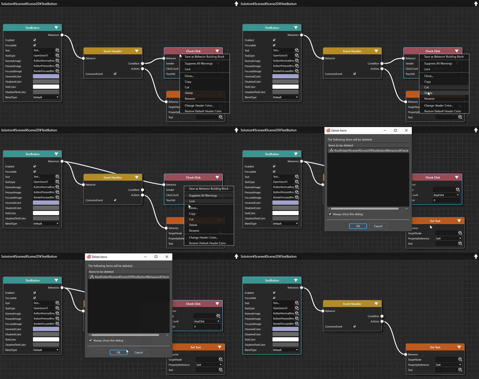
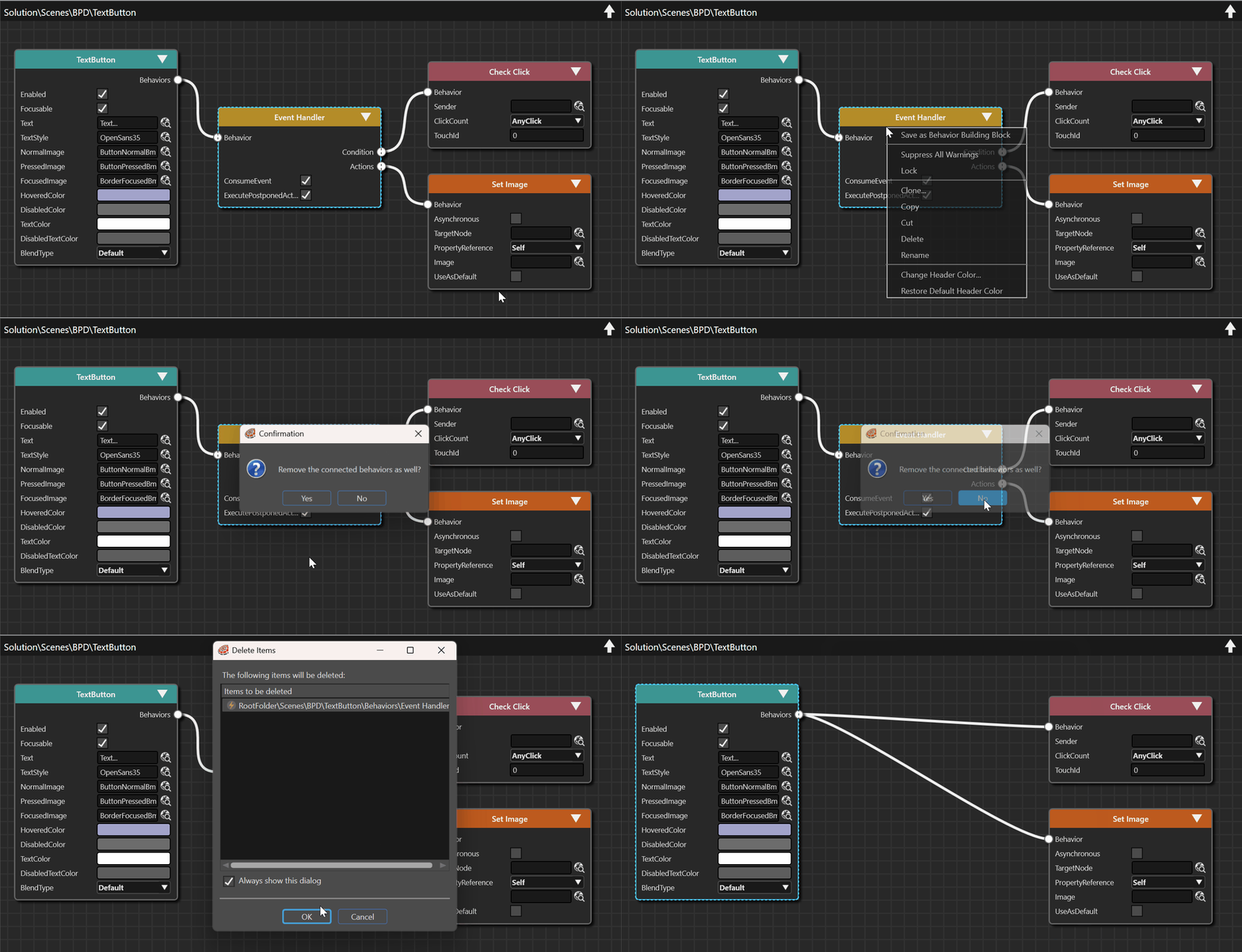
2. Target Fusion Node has Children
- Delete the node using either the Delete key or the context menu option.
- A prompt will appear asking if you want to delete the connected behaviors as well.
- Click No to delete only the node itself.
- The Delete Items dialog box will be opened.
- Review the contents and click OK to confirm deletion.
- Any child Fusion nodes connected to the target node will be automatically reconnected to the top node.
Re-Structuring the Nodes in a Fusion Diagram
The Top Node is the only node that can remain in a Fusion diagram without a link, provided he is the sole node in the diagram. All other Fusion nodes must be connected via a link. Deleting the link directly is not possible.
Re-Link a Connected Node to the Diagram's Top Node
Any Fusion node can be re-linked to the Fusion diagram's top node using one of the following methods:
- Right-click on the left connector of the node to link it to the top node.
- click and drag the connected link away from the left connector, then release the mouse button.
- Right-click on the right connector of the node, which your node is linked to (this allows re-linking multiple nodes with a single click)
Change the Node a Fusion Node is Linked To
To link an already connected node to another node click the right connector of the node you want to connect from and drag a link to the node that should be connected.
Undo/Redo operation
You can perform Undo and Redo actions in two ways:
- Toolbar Icons: Click the Undo or Redo icons in the toolbar.
- Keyboard Shortcuts:
- Ctrl + Z ... Undo the last action
- Ctrl + Y ... Redo the previous undone action.
Context Menu
After selecting a Fusion node, right-click to display the context menu with the following operations:

| Save as Behavior Building Block |
Saves the currently selected Fusion node as a Behavior Building Block. |
| Suppress All Warning |
Hides behavior-related warnings in Problems Browser panel. |
| Create Group |
Groups the currently selected nodes into a Fusion Group. This option appears when multiple Fusion nodes are selected. |
| Lock |
Locks the selected Fusion nodes, preventing any modification. The connector of a locked Fusion node will be grayed out and no additional Fusion node operations can be performed. Note that locking the top node will lock all connected Fusion nodes. |
| Unlock |
Unlocks the currently selected Fusion node. This option is displayed when the currently selected Fusion node is locked . If multiple Fusion nodes are selected, this option is displayed only when all selected Fusion nodes are locked. |
| Force Unlock |
Force all locks to be released. This option is displayed when Top node is locked and Fusion nodes connected to it are selected. |
|
Clone |
Creates an identical copy of the selected node. The cloned Fusion node will have the same name as the original, with an appended numerical suffix for differentiation. |
| Copy | Copies the selected Fusion node. This operation is the same as the keyboard shortcut Ctrl + C. |
| Cut |
Cuts the selected Fusion node. This operation is the same as the keyboard shortcut Ctrl + V. |
| Delete |
Performs a delete operation on a selected Fusion node. |
| Paste |
Pastes the copied/cut Fusion node to the specified location. This option appears after performing a Copy or Cut operation. |
| Rename |
Renames the selected Fusion node. Enter a new name in the provided input field. |
| Change Header Color | Changes the header color of the Fusion node to any color. Choose a color in the Color Palette dialog that will be opened. |
| Restore Default Header Color | Restores the default header color specified in [ Preferences > Fusion ]. |
Double Click operation
Double-clicking on a Fusion node changes the display as follows:
- State Machine Element
-> Opens the State Machine Editor screen for the selected element - Behavior Building Block Node
-> Displays the Fusion diagram of the target Behavior BuildingBlock's template. - Behavior Group
-> Shows the internal structure of the group
Top Node
The Fusion node diagram in the Fusion panel always starts with the top node. The Top Node serves as root node in the Fusion diagram and is fixed, meaning it cannot be deleted from the Fusion Editor.
The Top Node corresponds to the node selected in the scene tree. If Fusion is launched from within the State Machine Editor, it represents the State Machine Element (such as a State or Transition) that was selected when starting Fusion.

Top Node Connector
The Top Node has a single connector on its right side, which is used to create and connect other Fusion Nodes.
For details on connecting Fusion Nodes, see Basic Operations.

Selecting a Top Node
The following types of nodes can serve as the Top Node in a Fusion diagram:
- Predefined CGI Control Templates
- Custom User Controls and Instantiated controls with user defined properties
- Behavior Building Block Templates
- State Machine Elements (e.g. States, Transitions)
- 2D/3D Scene Nodes
- Behavior Groups
To select a Top Node:
- In the Scene Tree, click the desired node.
- The adjacent Extra Scene Tree lists the Behaviors and Effects of the node selected in the Scene Tree along with a [Fusion...] button.
- Click the [Fusion...] button to open the Fusion Editor.
- The Fusion Editor will display the selected node as the Top Node in the Fusion diagram.

If the Fusion Editor is already open, selecting any node in the Scene Tree will automatically update the Fusion Editor to display the Fusion diagram for the corresponding node.
The choice of a Top Node depends on the specific use case. For example:
Essentially, the Top Node is the element that acts as the source or recipient of events or values to be processed.
Fusion Node Categories
The following type of behaviors can be connected connected to the top node in Fusion:
- Action Fusion Node
- Condition Fusion Node
- Behavior Fusion Node
- Behavior Group Fusion Node (BehaviorBuildingBlock)
In addition to these, reference Fusion nodes within Action, Condition, Behavior Fusion node can also be connected.
The color of each Fusion node category - including the Top Node - as displayed in the Fusion Editor can be customized in Preferences.
Configuration example
This page explains how to use Fusion to configure operations related to "Set Text", which is one examples of applying a behavior within a Fusion diagram.
Prepare Nodes in the Scene Editor
- In the Toolbox, navigate to Control > Touchable.
- Drag and drop a TextButton control onto the Scene Editor.
- In the Scene Editor, a TextButton has been created.
- In the Toolbox, navigate to Node 2D.
- Drag and drop a Text Node onto the Scene Editor.
- In the Scene Editor, a TextNode has been created.
- Adjust the position of the Text Node so that it is placed next to the TextButton in the Scene Editor.
- In the Scene Editor, a TextButton and a TextNode are next to each other.
- In the Scene Tree panel, TextButton and TextNode are part of the scene tree.

Configure the TextButton in Fusion
- In the Scene Tree panel, select the TextButton and click the [ Fusion... ] button in the Extra Scene Tree.
- Fusion will be opened, displaying the TextButton's Fusion diagram.

- Fusion will be opened, displaying the TextButton's Fusion diagram.
- In Fusion, at the TextButton's Fusion Node change the Text property to "Change Text".
- This is the same as editing the TextButton's Text property in the Properties panel.

- This is the same as editing the TextButton's Text property in the Properties panel.
- In Fusion, click the Action connector on the right side of the Event Handler Fusion Node.
- The Select Behavior dialog will be opened.
- Click into the input field in the top of the dialog and start typing Set Text.
- The list of behaviors will be narrowed down while typing.
- In the dialog, double-click the SetText behavior.
- A new Fusion node Set Text has been created, connected to the Event Handler's Actions connector.

- A new Fusion node Set Text has been created, connected to the Event Handler's Actions connector.
- In Fusion, click the Select Item icon at the TargetNode property of the added Set Text Fusion node.
- The Choose Item dialog will be opened.

- The Choose Item dialog will be opened.
- In the Choose Item dialog, select the TextNode and click [OK].
- The TargetNode for the Set Text behavior is the scene's TextNode.

- The TargetNode for the Set Text behavior is the scene's TextNode.
- In Fusion, configure the Set Text Fusion Node's Text Property to "Hallo Fusion".
- The Set Text behavior will set the TextNode's text to "Hallo Fusion",

- The Set Text behavior will set the TextNode's text to "Hallo Fusion",
Configure the TextNode in Fusion
- In the Scene Tree panel, select the TextNode and click the [ Fusion... ] button in the Extra Scene Tree.
- Fusion will be opened, displaying the TextNode's Fusion diagram.

- Fusion will be opened, displaying the TextNode's Fusion diagram.
- In Fusion, click the Behaviors connector on the right side of the Text Node Fusion Node.
- The Select Behavior dialog will be opened.
- Click into the input field in the top of the dialog and start typing Provide Text.
- The list of behaviors will be narrowed down while typing.
- In the dialog, double-click the Provide Text behavior.
- A new Fusion node Provide Text has been created, connected to the Text Node's Behaviors connector.

- A new Fusion node Provide Text has been created, connected to the Text Node's Behaviors connector.
Check the Scene in the Player
- Save your work and start the Player to test the functionality of your configuration.
- The Player will be opened, displaying the configured scene.
- Click on the TextButton.
- The TextNode's text will be changed to "Hallo Fusion".
- The TextNode's text will be changed to "Hallo Fusion".
