# Part 1: Prepare Scenes
This page explains the procedure for creating and configuring a multi-scene user interface (UI) using CGI Studio.
It covers the creation, duplication, and editing of nine scenes, including Main Menu, Navigation, Media Menu, and Phone, where text nodes and overlay layouts are placed to build the UI. The process also includes deleting unnecessary scenes, configuring rendering settings, optimizing buffer management (introducing Clear/Swap scenes), and setting camera sequence numbers. Ultimately, the necessary preparations for state transitions (state machine configuration) between scenes will be completed.
The scenes you create will be used when you actually construct the State Machine in Part 2 and beyond.
### Creating the Main Menu Scene
The Main Menu scene is used to display the current context (Navigation, Media, Phone).
### Renaming the Scene and Placing Nodes
1. Start Scene Composer and select **\[Empty\]** from **\[Samples and Templates\]** on the startup screen.
- A new solution will open as an Empty solution.
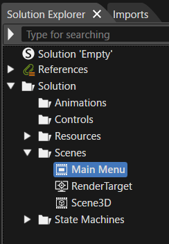
2. In the **Solution Explorer**, select **\[Scene2D\]** under the **\[Scenes\]** folder, then choose **\[Rename\]** from the context menu.
- Scene2D will enter rename mode.
3. Rename it to **\[Main Menu\]**.
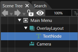
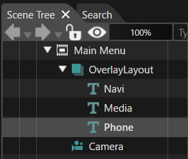
4. Drag and drop **\[Overlay Layout\]** from **\[Nodes 2D\]** in the **\[Toolbox\]** panel onto the **\[Main Menu\]** scene tree.
- **\[OverlayLayout\]** will be added to the scene tree.
- The **\[Position\]** under **\[Transform\]** in the **\[Properties\]** panel will be automatically set to X=0, Y=0.
5. Similarly, drag and drop **\[Text Node\]** from **\[Nodes 2D\]** onto **\[Overlay Layout\]**.
- **\[TextNode\]** will be added as a child node of **\[OverlayLayout\]**.
6. Select **\[TextNode\]**, then choose **\[Clone\]** from the context menu.
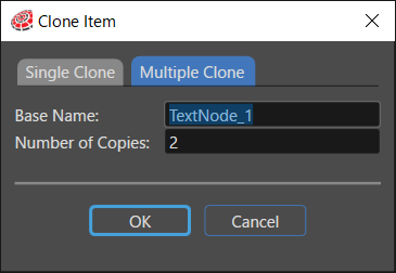
- The **\[Clone Item\]** dialog will appear.
7. In the **\[Clone Item\]** dialog, select the **\[Multiple Clone\]** tab, set **\[ Number of Copies \]** to **2**, and click **\[OK\]**.
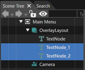
- **\[TextNode\_1\]** and **\[TextNode\_2\]** will be added as child nodes of **\[OverlayLayout\]**.
### Renaming Text Nodes
1. Rename the three added text nodes to **Navi**, **Media**, and **Phone**.
- To rename, select the node, choose **\[Rename\]** from the context menu, or press **F2**.
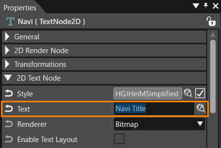
2. Select **\[Navi\]** in the scene tree.
- The **\[Properties\]** panel will display **\[Navi\]** properties.
3. In the **\[2D Text Node\]** section of the **\[Properties\]** panel, change **\[Text\]** to **"Navi Title"**.
- "Navi Title" will be displayed in the Scene Editor (overlapping with other text nodes).
4. Similarly, update **\[Text\]** for **\[Media\]** and **\[Phone\]**.
- The Scene Editor will display the text nodes overlapping.
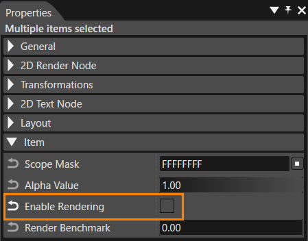
5. Select **\[Media\]** and **\[Phone\]** together in the scene tree, then uncheck **\[Enable Rendering\]** in the **\[Properties\]** panel under **\[Item\]**.
- Rendering for **\[Media\]** and **\[Phone\]** will be disabled, displaying only **"Navi Title"** in the Scene Editor.
### Deleting Unnecessary Scenes
Delete unnecessary scenes from the Empty sample solution that are not needed for this tutorial.
1. In **\[Solution Explorer\]**, select **\[Scene3D\]** under the **\[Scenes\]** folder, then press **Delete**.
- The **\[Delete Item\]** dialog will appear.
2. Click **\[OK\]** in the dialog to proceed with deletion.
- **\[Scene3D\]** will be removed from the **\[Scenes\]** folder in **\[Solution Explorer\]**.
The Main Menu scene setup is now complete.
### Adding the Navigation Scene
Add two new scenes, setting them as **Navigation** and **Phone**, with text displaying "Navigation" and "Phone" respectively.
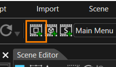
1. Click **\[Add a new 2D Scene\]** in the toolbar.
- The **\[Add New Scene 2D\]** dialog will appear.
2. In the **\[Add New Scene 2D\]** dialog, rename **\[Name\]** to **"Navigation"**, then click **\[OK\]**.
- The **\[Navigation\]** scene will be added under **\[Scenes\]** in **\[Solution Explorer\]**.
- The **Navigation** scene will appear in the scene tree.
3. Drag and drop **\[Text Node\]** from **\[2D Nodes\]** in the **\[Toolbox\]** onto the **Navigation** scene tree.
- **"Text"** will be displayed in the Scene Editor.
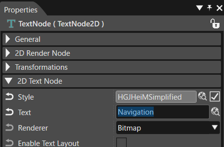
4. In the **\[Properties\]** panel, change **\[Text\]** under **\[2D Text Node\]** to **"Navigation"**.
- The text displayed in the Scene Editor will change to "Navigation".
5. Set the text node position using **\[Transform\]** in the **\[Properties\]** panel as the below table.
| Position X | 25 |
|---|
| Position Y | 150 |
The Navigation scene setup is now complete.
### Adding the Phone Scene
The Phone scene is created by duplicating the Navigation scene.
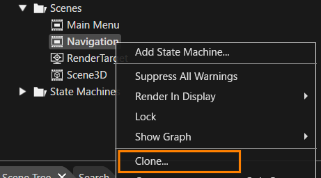
1. In **\[Solution Explorer\]**, select **\[Scenes > Navigation\]**, then choose **\[Clone\]** from the context menu.
- The **\[Clone Item\]** dialog will appear.
2. In the **\[Clone Item\]** dialog, select **\[Single Clone\]**, rename **\[Name\]** to **"Phone"**, then click **\[OK\]**.
- The **Phone** scene will be created.
- The scene tree will display the newly created **Phone** scene.
3. Select the text node in the **Phone** scene tree, then update **\[Text\]** in the **\[Properties\]** panel under **\[2D Text Node\]** to **"Phone"**.
- The text displayed in the Scene Editor will change to "Phone".
The Phone scene setup is now complete.
### Adding the Media Menu Scene
This scene is similar to the Main Menu scene. It includes an overlay layout node with three child text nodes: Radio, Bluetooth, and USB. Therefore, the Main Menu scene will be duplicated and set up it as Media Menu scene.
1. In **Solution Explorer**, select **\[Scenes > Main Menu\]**, then choose **\[Clone\]** from the context menu.
- The **\[Clone Item\]** dialog will appear.
2. In the **\[Clone Item\]** dialog, select **\[Single Clone\]**, rename **\[Name\]** to **"Media Menu"**, and click **\[OK\]**.
- A new scene named **Media Menu** will be created.
- The scene tree panel will display the **Media Menu** scene.
- The scene tree will contain an overlay layout node with three text nodes.
3. Select the **Overlay Layout** in the scene tree, then update the **\[Position\]** under **\[Transform\]** in the **Properties** panel:
4. Select each text node in the scene tree and update the **Properties** as follows:
| General > Name | 2D Text Node > Text |
| Radio | Radio Title |
| Bluetooth | Bluetooth Title |
| USB | USB Title |
The **Media Menu** scene setup is now complete. Since this was duplicated from the **Main Menu** scene, the **Enable Rendering** setting for **Bluetooth** and **USB** text nodes is disabled, so only "Radio Title" will be displayed in the Scene Editor.
### Creating the Media Radio Scene
The **Media Radio** scene is displayed when the **Media Menu** is selected. This scene is created by duplicating the previously created **Navigation** scene.
1. In **Solution Explorer**, select **\[Scenes > Navigation\]**, then choose **\[Clone\]** from the context menu.
- The **\[Clone Item\]** dialog will appear.
2. In the **\[Clone Item\]** dialog, select **\[Single Clone\]**, rename **\[Name\]** to **"Media Radio"**, and click **\[OK\]**.
- A new scene named **Media Radio** will be created.
- The scene tree panel will display the **Media Radio** scene.
3. Select the **Text Node** in the scene tree and update the **\[Text\]** under **\[2D Text Node\]** in the **Properties** panel to **"Radio"**.
- The text displayed in the Scene Editor will change to "Radio".
The **Media Radio** scene setup is now complete.
### Adding the Media Bluetooth and Media USB Scenes
Two additional scenes, **Media Bluetooth** and **Media USB**, will be created similarly to the **Media Radio** scene by duplicating it.
1. In **Solution Explorer**, select **\[Scenes > Media Radio\]**, then choose **\[Clone\]** from the context menu.
- The **\[Clone Item\]** dialog will appear.
2. In the **\[Clone Item\]** dialog, select **\[Multiple Clone\]**, set **\[Number of Copies\]** to **2**, and click **\[OK\]**.
- Two new scenes named **Media Radio\_1** and **Media Radio\_2** will be created.
- The scene tree panel will display the newly created **Media Radio\_1** scene.
3. In **Solution Explorer**, rename **Media Radio\_1** to **Media Bluetooth** and **Media Radio\_2** to **Media USB**.
4. Select the text node in the **Media Bluetooth** scene tree and update the **\[Text\]** under **\[2D Text Node\]** in the **Properties** panel to **"Bluetooth"**.
- The text displayed in the Scene Editor will change to "Bluetooth".}
5. Similarly, select the text node in the **Media USB** scene tree and update the **\[Text\]** to **"USB"**.
- The text displayed in the Scene Editor will change to "USB".
The **Media Bluetooth** and **Media USB** scene setups are now complete.
### Adding the Clear Scene
A **Clear Scene** containing only a camera is added to erase the contents of the old framebuffer. This scene is always rendered to ensure that previous frame contents do not appear.
1. Click the **\[Add a new 2D Scene\]** button in the toolbar.
- The **\[Add New Scene 2D\]** dialog will appear.
2. In the dialog, set **\[Name\]** to **"Clear"**, then click **\[OK\]**.
- The **Clear** scene will be added under the **\[Scenes\]** hierarchy in **Solution Explorer**.
The **Clear Scene** setup is now complete.
### Adding the Swap Scene
An additional **Swap Scene** is required to ensure proper rendering (switching of render target buffers) and correct display in **Scene Composer**.
However, this scene is only necessary for Scene Composer display purposes and is not required for the Courier application, as buffer swapping is handled automatically in Courier.
1. Click the **\[Add a new 2D Scene\]** button in the toolbar.
- The **\[Add New Scene 2D\]** dialog will appear.
2. In the dialog, set **\[Name\]** to **"Swap"**, then click **\[OK\]**.
- The **Swap** scene will be added under the **\[Scenes\]** hierarchy in **Solution Explorer**.
- The scene tree panel will display the newly created **Swap** scene.
The **Swap Scene** setup is now complete.
### Disabling Clear Color Buffer
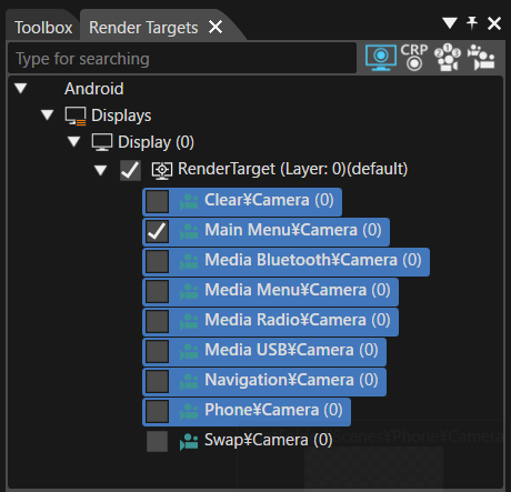
Since the **Clear Scene** erases the contents of the old framebuffer, the **Clear Color Buffer** setting should be disabled for all scene cameras **except the Clear Scene camera**. This is necessary as all scene cameras overlap.
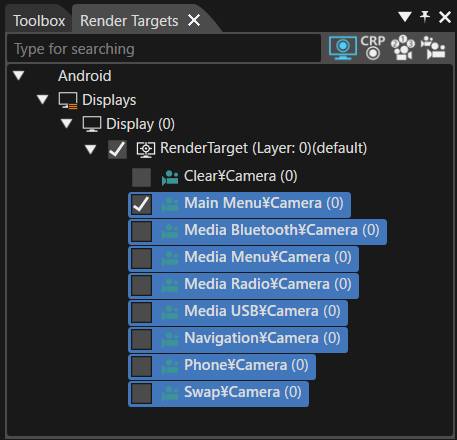
1. In the **\[Render Targets\]** panel, select all cameras except the **Clear Camera**.
- Hold down **Shift** key while selecting to choose multiple cameras.
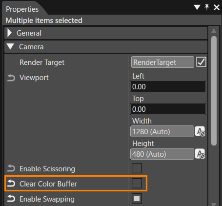
2. In the **Properties** panel, under the **\[Camera\]** category, uncheck **\[Clear Color Buffer\]**.
- This will disable the **Clear Color Buffer** setting for all selected cameras at once.
### Setting Enable Swapping
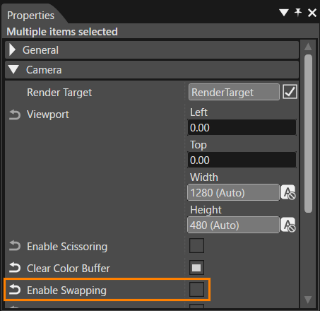
The **Swap Scene** executes buffer swapping. Therefore, the **Enable Swapping** setting must be disabled for all scene cameras except the **Swap Scene**.
1. In the **\[Render Targets\]** panel, select all cameras except the **Swap Camera**.
- Hold down **Shift** key while selecting to choose multiple cameras.
2. In the **Properties** panel, under the **\[Camera\]** category, uncheck **\[Enable Swapping\]**.
- This will disable the **Enable Swapping** setting for all selected cameras at once.
### Setting Camera Sequence Number
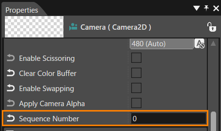
The rendering order of cameras is determined by the **\[Sequence Number\]** property. Cameras with smaller sequence numbers are rendered as backgrounds for those with larger numbers.
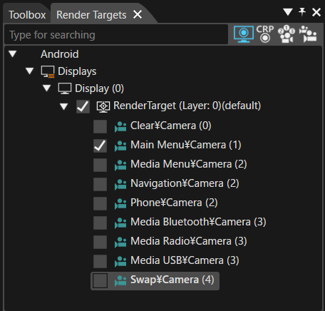
In the **Render Targets** panel, each camera's **\[Sequence Number\]** is displayed next to its name in parentheses, indicating their rendering order.
#### How to Set Sequence Number
The **Sequence Number** can be set using the following steps:
1. In the **Render Targets** panel, select the target camera(s) to be configured.
- The **Properties** panel will display the properties of the selected camera.
- To select multiple cameras, hold down **Shift** or **Ctrl** key while clicking.
2. In the **Properties** panel, under the **\[Camera\]** category, change the **\[Sequence Number\]** value.
#### Sequence Number Configuration
For this tutorial, set the **Sequence Number** for each camera as follows:
| Sequence Number | Camera Name |
|---|
| 0 | Clear |
| 1 | Main Menu |
| 2 | Media Menu, Navigation, Phone |
| 3 | Media Bluetooth, Media Radio, Media USB |
| 4 | Swap |
With this, all necessary scenes are now prepared for the **State Machine Configuration** in the next section.