# Advanced Cluster Part 2
In this part of the Advanced Cluster Best Practice the Custom\_Gauge control will be extended with a ForegroundImage and a NeedleEffectImage and new images will be configured to change the control's appearance completely.
#### Restructuring Custom\_Gauge Control
1. In the Solution Explorer double-click the "**Custom\_Gauge**".
- The control "**Custom\_Gauge**" will be opened in the Scene Editor, ready to be edited.
- Scene Tree will display the tree of nodes the control is composed of.
2. In the Scene Tree panel rename the "Group" node to "**Group\_Bitmaps**".
- In the Scene Tree panel the Group node has been renamed.
| **Rename from** | **Rename to** |
| Group | Group\_Bitmaps |
3. In the Scene Tree panel select the root node Custom\_Gauge. In the Properties panel's **\[Layouter\]** section change the Layout type from "Overlay" to "None".
- The Layout Type has been changed.
4. In the Scene Tree panel right-click on the "BackgroundImage" and choose **\[Clone...\]** from the context menu. In the opening "Clone Item" dialog enter "ForegroundImage" as name and press **\[OK\]**.
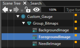
- A clone of "BackgroundImage" has been created. Its name is "ForegroundImage". The Scene Tree now looks as in the image below.
#### Exchanging Custom\_Gauge Control's Images
In steps 1 - 3 of this section the Custom\_Gauge new images for the **ForegroundImage** and **BackgroundImage** nodes will be configured. These steps need to be performed for the BackgroundImage node as well as for the Foreground Image node.
In steps 4 - 5 of this section the NeedleImage will be cloned and the images of NeedleImage and NeedleEffectImage will be exchanged.
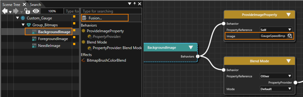
1. In the Scene Tree panel select the image. In the right side of the Scene Tree click on the **\[Fusion...\]** button.
- Fusion will be opened, displaying the Fusion diagram for the image.
2. In the Fusion diagram change the ProvideImageProperty's image by clicking the magnifying glass icon to the property's right.
- The **\[Choose Item\]** dialog will be displayed.
3. In the **\[Choose Item\]** dialog choose the appropriate new image given in the table below and click **\[OK\]**.
- The images displayed by the BackgroundImage and ForegroundImage nodes have been changed.
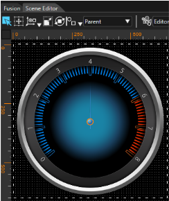
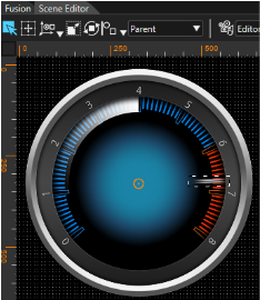
- When activating the Scene Editor the Custom\_Gauge with new Foreground and Background image can be viewed. It should look like the image below. To switch to the Fusion diagram of the second image simply double click it in the Scene Tree panel.
| **Node** | **new ProvideImageProperty image** |
| BackgroundImage | Solution > Resources > Bitmaps > Points\_Blue\_RedBmp |
| ForegroundImage | Solution > Resources > Bitmaps > Numbers\_0-8Bmp |
4. In the Scene Tree panel create a clone of the "NeedleImage" and name it "NeedleEffectImage".
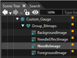
- A clone of "NeedleImage" has been created. Its name is "NeedleEffectImage". The Scene tree looks as in the image below. Please follow the order of the nodes in the scene tree to ensure their proper visibility.
5. Let's change the images displayed by NeedleImage and NeedleEffectImage. This can be done similarly to above. Select the image, open Fusion and click on the magnifying glass next to the ProvideImageProperty's image property. Configure the images given in the table below.
- The images displayed by the NeedleImage and NeedleEffectImage nodes have been changed.
- When activating the Scene Editor the Custom\_Gauge with new Needle and NeedleEffect image can be viewed. It should look like the image below (the needle is pointing to 3 o'clock). | **Node** | **ProvideImageProperty's image** |
| NeedleImage | Solution > Resources > Bitmaps > NeedleBmp |
| NeedleEffectImage | Solution > Resources > Bitmaps > Needle\_LighterBmp |
#### Configuring the Gauge Needle's Rotation Behavior
1. In the Scene Tree panel select the NeedleImage node. In the Scene Tree panel's right side rename the existing SetRotation behavior according to the table below. Repeat the same steps for the NeedleEffectImage node.
- The SetRotation behaviors of NeedleImage and NeedleEffectImage have been renamed. | **Node** | **New Name of SetRotation Behavior** |
| NeedleImage | SetRotation\_Needle |
| NeedleEffectImage | SetRotation\_Effect |
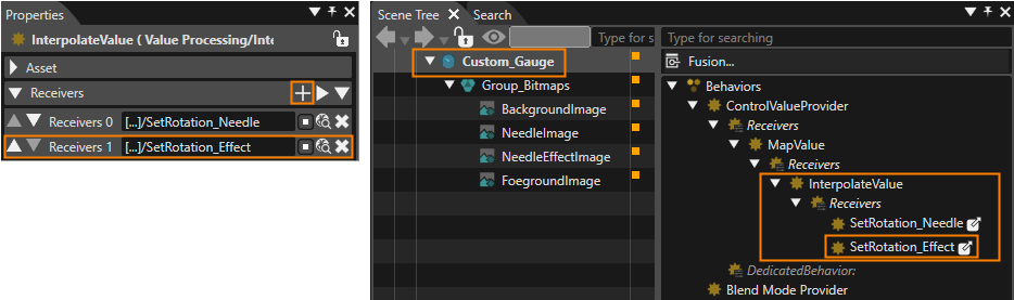
2. In the Scene Tree panel select the **Custom\_Gauge** node. In the Scene Tree panel's right side select the **InterpolateValue** behavior. In the Properties panel's **\[Receivers\]** section press the **\[+\]** button in the top right corner. This **\[+\]** button is marked in orange in the image of step 4.
- In the Properties panel's Receivers section you can see that a new line for a **new Receiver** is added for the InterpolateValue behavior.
3. Press the magnifying glass icon next to the new **Receivers 1** entry.
- The **\[Choose Item\]** dialog will be opened.
4. Select the behavior SetRotation\_Effect, which can be found under the path given below, and click **\[OK\]**.
- The NeedleEffectImage's **SetRotation\_Effect** is referenced as one of the Receivers of the **CustomGauge's InterpolateValue** behavior as you can see in the imaged below. | **Set Rotation\_Effect** | **Path** |
|
| Custom\_Gauge > Group\_Bitmaps > NeedleEffectImage > **SetRotation\_Effect** |
1. In the Scene Tree panel select the **NeedleEffectImage** node. In the Scene Tree panel's right side under **\[Behaviors\]** select "**Blend Mode**" and press Delete on your keyboard to delete this behavior.
- The behavior Blend Mode has been deleted.
2. While **NeedleEffectImage** is selected in the Scene Tree panel select the **BitmapBrushColorBlend** effect in the Scene Tree panel's right side and adjust its properties in the Properties panel according to the table below.
- The BitmapBrushColorBlend effect is configured correctly.
- In the Scene Editor you can see that the **NeedleEffectImage** is not a white gradient anymore. You can rather **perceive a slight change of color** compared to the original BackgroundImage (see image below, the needle is pointing to 3 o'clock).
| **BitmapBrushColorBlend**
**Property**
| **Value** |
| ColorBlendFactorSrc | DestColor |
| ColorBlendFactorDst | SourceAlpha |
3. In the Scene Tree panel select the **Custom\_Gauge** node. In the Scene Tree panel's right side select the **MapValue** behavior. In the **Properties** panel configure its properties according to the table below.
- The MapValue behavior's minimum and maximum value have been configured.
| **MapValue Properties**
| **Value** |
| OutputMin | -128.50 |
| OutputMax | 128.50 |