# State Machine Solution

# Overview

This tutorial aims to help users master the state transition and behavior control mechanisms between multiple scenes using the state machine functionality in CGI Studio. Specifically, the tutorial covers a step-by-step approach to developing practical HMI (Human-Machine Interface) applications, including UI construction, scene management, switching behaviors based on user interactions, managing history, conditional branching, and displaying the number of incoming calls.

Through this tutorial, users will learn the following:

<table border="1" id="bkmrk-page-theme-main-work" style="border-collapse: collapse; width: 800px; height: 148.403px; border-width: 0px;"><colgroup><col style="width: 7.98464%;"></col><col style="width: 31.9668%;"></col><col style="width: 60.0353%;"></col></colgroup><tbody><tr><td class="align-center" style="border-width: 0px; background-color: rgb(35, 111, 161);">**<span style="color: rgb(255, 255, 255);">Page</span>**</td><td class="align-center" style="border-width: 0px; background-color: rgb(35, 111, 161);">**<span style="color: rgb(255, 255, 255);">Theme</span>**</td><td class="align-center" style="border-width: 0px; background-color: rgb(35, 111, 161);">**<span style="color: rgb(255, 255, 255);">Main work content</span>**

</td></tr><tr style="height: 29.6806px;"><td style="height: 29.6806px; border-width: 0px;">Part 1</td><td style="height: 29.6806px; border-width: 0px;">Basics of Scene Composition and UI Design</td><td style="height: 29.6806px; border-width: 0px;">Understanding how to create and manage multi-scene UIs in CGI Studio.

- Building 9 scenes including Main Menu, Navigation, Media, Phone, etc.
- Manipulating text nodes, overlay layouts, and node positioning.
- Adding Clear/Swap scenes to manage buffers and control sequences.

</td></tr><tr style="height: 29.6806px;"><td style="height: 29.6806px; border-width: 0px;">Part 2</td><td style="height: 29.6806px; border-width: 0px;">Basics of State Machine and Transition Control</td><td style="height: 29.6806px; border-width: 0px;">Learning how to control scene transitions using a state machine.

- Recreating a global state machine and linking it to scenes.
- Controlling scene visibility using OnEntry/OnExit actions.
- Configuring transitions using key inputs (left/right arrow keys).
- Verifying transitions and behaviors in the Player.

</td></tr><tr style="height: 29.6806px;"><td style="height: 29.6806px; border-width: 0px;">Part 3</td><td style="height: 29.6806px; border-width: 0px;">Transition Optimization with Subcharts and History State</td><td style="height: 29.6806px; border-width: 0px;">Using Subcharts and History State for advanced scene management.

- Converting the Media State into a Subchart to manage sub-scenes for Radio, Bluetooth, and USB.
- Implementing History State to retain information about the previously active scene.
- Configuring bidirectional transitions and state restoration between scenes.
- Verifying scene selection and behavior using the up/down arrow keys.

</td></tr><tr style="height: 29.6806px;"><td style="height: 29.6806px; border-width: 0px;">Part 4</td><td style="height: 29.6806px; border-width: 0px;">Adding Incoming Call Scene and Popup Control</td><td style="height: 29.6806px; border-width: 0px;">Implementing popup control and state transitions for incoming calls.

- Creating an IncomingCall scene based on the existing Phone scene.
- Controlling the display with the Enter key for call display and the ESC key for hiding.
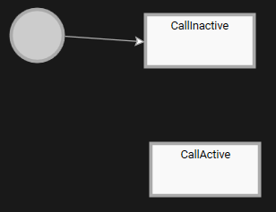
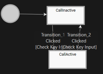
- Constructing CallActive/CallInactive state machines.
- Customizing the visuals using SolidColorNode.

</td></tr><tr style="height: 29.6806px;"><td style="height: 29.6806px; border-width: 0px;">Part 5</td><td style="height: 29.6806px; border-width: 0px;">Counting Incoming Calls and Updating UI</td><td style="height: 29.6806px; border-width: 0px;">Understanding how to send events through the state machine and update the UI.

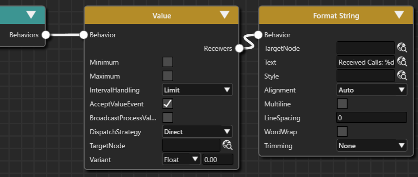
- Adding a text node with “Received Calls: %d” to the Main Menu scene.
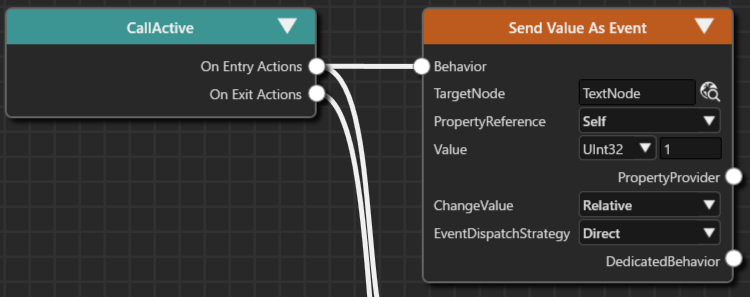
- Counting the number of incoming calls when entering the CallActive State.
- Sending relative values as events using Send Value As Event.
- Displaying call count information in real time using Format String.

</td></tr></tbody></table>

# Part 1: Prepare Scenes

This page explains the procedure for creating and configuring a multi-scene user interface (UI) using CGI Studio.

It covers the creation, duplication, and editing of nine scenes, including Main Menu, Navigation, Media Menu, and Phone, where text nodes and overlay layouts are placed to build the UI. The process also includes deleting unnecessary scenes, configuring rendering settings, optimizing buffer management (introducing Clear/Swap scenes), and setting camera sequence numbers. Ultimately, the necessary preparations for state transitions (state machine configuration) between scenes will be completed.

The scenes you create will be used when you actually construct the State Machine in Part 2 and beyond.

### Creating the Main Menu Scene

The Main Menu scene is used to display the current context (Navigation, Media, Phone).

### Renaming the Scene and Placing Nodes

1. Start Scene Composer and select **\[Empty\]** from **\[Samples and Templates\]** on the startup screen.
    
    
    - A new solution will open as an Empty solution.
2. In the **Solution Explorer**, select **\[Scene2D\]** under the **\[Scenes\]** folder, then choose **\[Rename\]** from the context menu.
    
    
    - Scene2D will enter rename mode.
3. Rename it to **\[Main Menu\]**.
    
    <div drawio-diagram="8072"><img src="https://doc316en.candera.eu/uploads/images/drawio/2025-03/drawing-4-1742205749.png" alt=""/></div>
4. Drag and drop **\[Overlay Layout\]** from **\[Nodes 2D\]** in the **\[Toolbox\]** panel onto the **\[Main Menu\]** scene tree.
    
    
    - **\[OverlayLayout\]** will be added to the scene tree.
    - The **\[Position\]** under **\[Transform\]** in the **\[Properties\]** panel will be automatically set to X=0, Y=0.
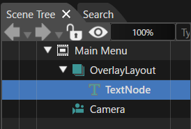
5. Similarly, drag and drop **\[Text Node\]** from **\[Nodes 2D\]** onto **\[Overlay Layout\]**.
    
    
    - **\[TextNode\]** will be added as a child node of **\[OverlayLayout\]**.
        
        <div drawio-diagram="8073"><img src="https://doc316en.candera.eu/uploads/images/drawio/2025-03/drawing-4-1742205791.png" alt=""/></div>
6. Select **\[TextNode\]**, then choose **\[Clone\]** from the context menu.
    
    
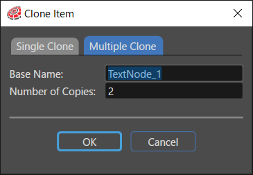
    - The **\[Clone Item\]** dialog will appear.
        
        <div drawio-diagram="8074"><img src="https://doc316en.candera.eu/uploads/images/drawio/2025-03/drawing-4-1742205824.png" alt=""/></div>
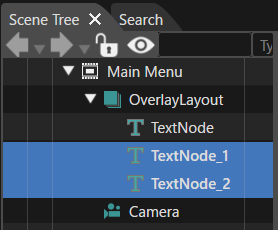
7. In the **\[Clone Item\]** dialog, select the **\[Multiple Clone\]** tab, set **\[ Number of Copies \]** to **2**, and click **\[OK\]**.
    
    
    - **\[TextNode\_1\]** and **\[TextNode\_2\]** will be added as child nodes of **\[OverlayLayout\]**.
        
        <div drawio-diagram="8075"><img src="https://doc316en.candera.eu/uploads/images/drawio/2025-03/drawing-4-1742205850.png" alt=""/></div>

### Renaming Text Nodes

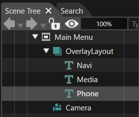
1. Rename the three added text nodes to **Navi**, **Media**, and **Phone**.
    
    
    - To rename, select the node, choose **\[Rename\]** from the context menu, or press **F2**.
        
        <div drawio-diagram="8076"><img src="https://doc316en.candera.eu/uploads/images/drawio/2025-03/drawing-4-1742205899.png" alt=""/></div>
2. Select **\[Navi\]** in the scene tree.
    
    
    - The **\[Properties\]** panel will display **\[Navi\]** properties.
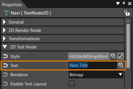
3. In the **\[2D Text Node\]** section of the **\[Properties\]** panel, change **\[Text\]** to **"Navi Title"**.
    
    
    - "Navi Title" will be displayed in the Scene Editor (overlapping with other text nodes).
        
        <div drawio-diagram="8077"><img src="https://doc316en.candera.eu/uploads/images/drawio/2025-03/drawing-4-1742205954.png" alt=""/></div>
4. Similarly, update **\[Text\]** for **\[Media\]** and **\[Phone\]**.
    
    
    - The Scene Editor will display the text nodes overlapping.
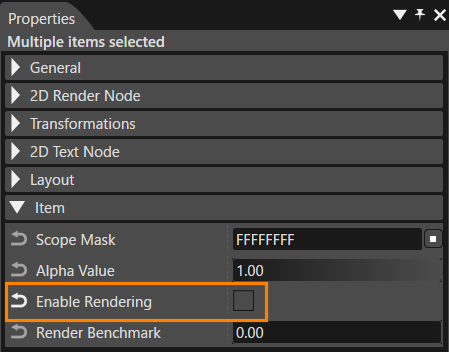
5. Select **\[Media\]** and **\[Phone\]** together in the scene tree, then uncheck **\[Enable Rendering\]** in the **\[Properties\]** panel under **\[Item\]**.
    
    
    - Rendering for **\[Media\]** and **\[Phone\]** will be disabled, displaying only **"Navi Title"** in the Scene Editor.
        
        <div drawio-diagram="8078"><img src="https://doc316en.candera.eu/uploads/images/drawio/2025-03/drawing-4-1742206021.png" alt=""/></div>

### Deleting Unnecessary Scenes

Delete unnecessary scenes from the Empty sample solution that are not needed for this tutorial.

1. In **\[Solution Explorer\]**, select **\[Scene3D\]** under the **\[Scenes\]** folder, then press **Delete**.
    
    
    - The **\[Delete Item\]** dialog will appear.
2. Click **\[OK\]** in the dialog to proceed with deletion.
    
    
    - **\[Scene3D\]** will be removed from the **\[Scenes\]** folder in **\[Solution Explorer\]**.

The Main Menu scene setup is now complete.

### Adding the Navigation Scene

Add two new scenes, setting them as **Navigation** and **Phone**, with text displaying "Navigation" and "Phone" respectively.

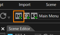
1. Click **\[Add a new 2D Scene\]** in the toolbar.
    
    
    - The **\[Add New Scene 2D\]** dialog will appear.
        
        <div drawio-diagram="8079"><img src="https://doc316en.candera.eu/uploads/images/drawio/2025-03/drawing-4-1742206065.png" alt=""/></div>
2. In the **\[Add New Scene 2D\]** dialog, rename **\[Name\]** to **"Navigation"**, then click **\[OK\]**.
    
    
    - The **\[Navigation\]** scene will be added under **\[Scenes\]** in **\[Solution Explorer\]**.
    - The **Navigation** scene will appear in the scene tree.
3. Drag and drop **\[Text Node\]** from **\[2D Nodes\]** in the **\[Toolbox\]** onto the **Navigation** scene tree.
    
    
    - **"Text"** will be displayed in the Scene Editor.
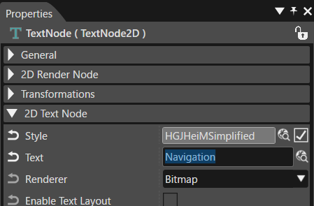
4. In the **\[Properties\]** panel, change **\[Text\]** under **\[2D Text Node\]** to **"Navigation"**.
    
    
    - The text displayed in the Scene Editor will change to "Navigation".
        
        <div drawio-diagram="8080"><img src="https://doc316en.candera.eu/uploads/images/drawio/2025-03/drawing-4-1742206143.png" alt=""/></div>
5. Set the text node position using **\[Transform\]** in the **\[Properties\]** panel as the below table.
    
    <table style="width: 20.6186%;"><tbody><tr><td style="width: 66.5529%; background-color: rgb(35, 111, 161);"><span style="color: rgb(255, 255, 255);">Position X</span></td><th style="width: 33.2764%;">25</th></tr><tr><td style="width: 66.5529%; background-color: rgb(35, 111, 161);"><span style="color: rgb(255, 255, 255);">Position Y</span></td><td style="width: 33.2764%;">150</td></tr></tbody></table>

The Navigation scene setup is now complete.

### Adding the Phone Scene

The Phone scene is created by duplicating the Navigation scene.

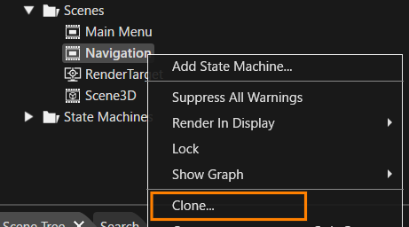
1. In **\[Solution Explorer\]**, select **\[Scenes &gt; Navigation\]**, then choose **\[Clone\]** from the context menu.
    
    
    - The **\[Clone Item\]** dialog will appear.
        
        <div drawio-diagram="8081"><img src="https://doc316en.candera.eu/uploads/images/drawio/2025-03/drawing-4-1742206203.png" alt=""/></div>
2. In the **\[Clone Item\]** dialog, select **\[Single Clone\]**, rename **\[Name\]** to **"Phone"**, then click **\[OK\]**.
    
    
    - The **Phone** scene will be created.
    - The scene tree will display the newly created **Phone** scene.
3. Select the text node in the **Phone** scene tree, then update **\[Text\]** in the **\[Properties\]** panel under **\[2D Text Node\]** to **"Phone"**.
    
    
    - The text displayed in the Scene Editor will change to "Phone".

The Phone scene setup is now complete.

### Adding the Media Menu Scene

This scene is similar to the Main Menu scene. It includes an overlay layout node with three child text nodes: Radio, Bluetooth, and USB. Therefore, the Main Menu scene will be duplicated and set up it as Media Menu scene.

1. In **Solution Explorer**, select **\[Scenes &gt; Main Menu\]**, then choose **\[Clone\]** from the context menu.
    
    
    - The **\[Clone Item\]** dialog will appear.
2. In the **\[Clone Item\]** dialog, select **\[Single Clone\]**, rename **\[Name\]** to **"Media Menu"**, and click **\[OK\]**.
    
    
    - A new scene named **Media Menu** will be created.
    - The scene tree panel will display the **Media Menu** scene.
    - The scene tree will contain an overlay layout node with three text nodes.
3. Select the **Overlay Layout** in the scene tree, then update the **\[Position\]** under **\[Transform\]** in the **Properties** panel:
    
    <table style="width: 23.8402%;"><tbody><tr><td style="width: 70.9001%; background-color: rgb(35, 111, 161);"><span style="color: rgb(255, 255, 255);">Position X</span></td><th style="width: 28.9766%;">0</th></tr><tr><td style="width: 70.9001%; background-color: rgb(35, 111, 161);"><span style="color: rgb(255, 255, 255);">Position Y</span></td><td style="width: 28.9766%;">50</td></tr></tbody></table>
4. Select each text node in the scene tree and update the **Properties** as follows:
    
    <table style="width: 43.0412%;"><tbody><tr><td style="width: 45.4827%; background-color: rgb(35, 111, 161);"><span style="color: rgb(255, 255, 255);">General &gt; Name</span></td><td style="width: 54.4554%; background-color: rgb(35, 111, 161);"><span style="color: rgb(255, 255, 255);">2D Text Node &gt; Text</span></td></tr><tr><td style="width: 45.4827%;">Radio</td><td style="width: 54.4554%;">Radio Title</td></tr><tr><td style="width: 45.4827%;">Bluetooth</td><td style="width: 54.4554%;">Bluetooth Title</td></tr><tr><td style="width: 45.4827%;">USB</td><td style="width: 54.4554%;">USB Title</td></tr></tbody></table>

The **Media Menu** scene setup is now complete. Since this was duplicated from the **Main Menu** scene, the **Enable Rendering** setting for **Bluetooth** and **USB** text nodes is disabled, so only "Radio Title" will be displayed in the Scene Editor.

### Creating the Media Radio Scene

The **Media Radio** scene is displayed when the **Media Menu** is selected. This scene is created by duplicating the previously created **Navigation** scene.

1. In **Solution Explorer**, select **\[Scenes &gt; Navigation\]**, then choose **\[Clone\]** from the context menu.
    
    
    - The **\[Clone Item\]** dialog will appear.
2. In the **\[Clone Item\]** dialog, select **\[Single Clone\]**, rename **\[Name\]** to **"Media Radio"**, and click **\[OK\]**.
    
    
    - A new scene named **Media Radio** will be created.
    - The scene tree panel will display the **Media Radio** scene.
3. Select the **Text Node** in the scene tree and update the **\[Text\]** under **\[2D Text Node\]** in the **Properties** panel to **"Radio"**.
    
    
    - The text displayed in the Scene Editor will change to "Radio".

The **Media Radio** scene setup is now complete.

### Adding the Media Bluetooth and Media USB Scenes

Two additional scenes, **Media Bluetooth** and **Media USB**, will be created similarly to the **Media Radio** scene by duplicating it.

1. In **Solution Explorer**, select **\[Scenes &gt; Media Radio\]**, then choose **\[Clone\]** from the context menu.
    
    
    - The **\[Clone Item\]** dialog will appear.
2. In the **\[Clone Item\]** dialog, select **\[Multiple Clone\]**, set **\[Number of Copies\]** to **2**, and click **\[OK\]**.
    
    
    - Two new scenes named **Media Radio\_1** and **Media Radio\_2** will be created.
    - The scene tree panel will display the newly created **Media Radio\_1** scene.
3. In **Solution Explorer**, rename **Media Radio\_1** to **Media Bluetooth** and **Media Radio\_2** to **Media USB**.
4. Select the text node in the **Media Bluetooth** scene tree and update the **\[Text\]** under **\[2D Text Node\]** in the **Properties** panel to **"Bluetooth"**.
    
    
    - The text displayed in the Scene Editor will change to "Bluetooth".}
5. Similarly, select the text node in the **Media USB** scene tree and update the **\[Text\]** to **"USB"**.
    
    
    - The text displayed in the Scene Editor will change to "USB".

The **Media Bluetooth** and **Media USB** scene setups are now complete.

### Adding the Clear Scene

A **Clear Scene** containing only a camera is added to erase the contents of the old framebuffer. This scene is always rendered to ensure that previous frame contents do not appear.

1. Click the **\[Add a new 2D Scene\]** button in the toolbar.
    
    
    - The **\[Add New Scene 2D\]** dialog will appear.
2. In the dialog, set **\[Name\]** to **"Clear"**, then click **\[OK\]**.
    
    
    - The **Clear** scene will be added under the **\[Scenes\]** hierarchy in **Solution Explorer**.

The **Clear Scene** setup is now complete.

### Adding the Swap Scene

An additional **Swap Scene** is required to ensure proper rendering (switching of render target buffers) and correct display in **Scene Composer**.

<p class="callout info">However, this scene is only necessary for Scene Composer display purposes and is not required for the Courier application, as buffer swapping is handled automatically in Courier.</p>

1. Click the **\[Add a new 2D Scene\]** button in the toolbar.
    
    
    - The **\[Add New Scene 2D\]** dialog will appear.
2. In the dialog, set **\[Name\]** to **"Swap"**, then click **\[OK\]**.
    
    
    - The **Swap** scene will be added under the **\[Scenes\]** hierarchy in **Solution Explorer**.
    - The scene tree panel will display the newly created **Swap** scene.

The **Swap Scene** setup is now complete.

### Disabling Clear Color Buffer

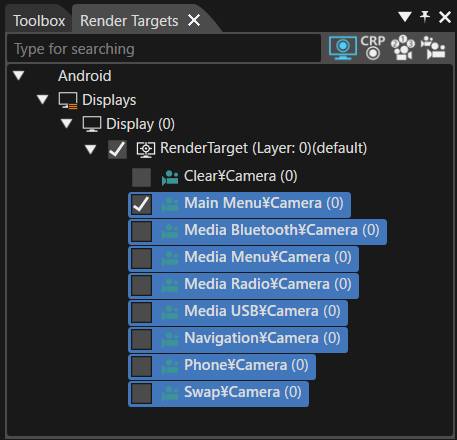
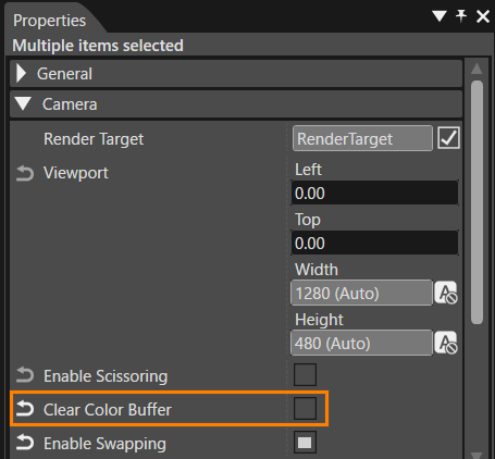
Since the **Clear Scene** erases the contents of the old framebuffer, the **Clear Color Buffer** setting should be disabled for all scene cameras **except the Clear Scene camera**. This is necessary as all scene cameras overlap.

1. In the **\[Render Targets\]** panel, select all cameras except the **Clear Camera**.
    
    
    - Hold down **Shift** key while selecting to choose multiple cameras.
        
        <div drawio-diagram="8082"><img src="https://doc316en.candera.eu/uploads/images/drawio/2025-03/drawing-4-1742207857.png" alt=""/></div>
2. In the **Properties** panel, under the **\[Camera\]** category, uncheck **\[Clear Color Buffer\]**.
    
    
    - This will disable the **Clear Color Buffer** setting for all selected cameras at once.
        
        <div drawio-diagram="8083"><img src="https://doc316en.candera.eu/uploads/images/drawio/2025-03/drawing-4-1742207897.png" alt=""/></div>

### Setting Enable Swapping

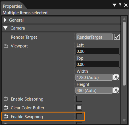
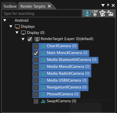
The **Swap Scene** executes buffer swapping. Therefore, the **Enable Swapping** setting must be disabled for all scene cameras except the **Swap Scene**.

1. In the **\[Render Targets\]** panel, select all cameras except the **Swap Camera**.
    
    
    - Hold down **Shift** key while selecting to choose multiple cameras.
        
        <div drawio-diagram="8084"><img src="https://doc316en.candera.eu/uploads/images/drawio/2025-03/drawing-4-1742207923.png" alt=""/></div>
2. In the **Properties** panel, under the **\[Camera\]** category, uncheck **\[Enable Swapping\]**.
    
    
    - This will disable the **Enable Swapping** setting for all selected cameras at once.
        
        <div drawio-diagram="8085"><img src="https://doc316en.candera.eu/uploads/images/drawio/2025-03/drawing-4-1742208003.png" alt=""/></div>

### Setting Camera Sequence Number

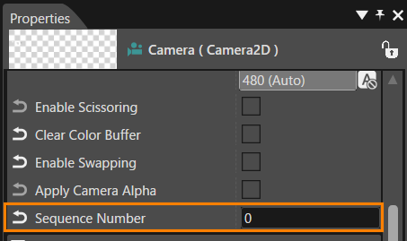
The rendering order of cameras is determined by the **\[Sequence Number\]** property. Cameras with smaller sequence numbers are rendered as backgrounds for those with larger numbers.

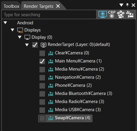
In the **Render Targets** panel, each camera's **\[Sequence Number\]** is displayed next to its name in parentheses, indicating their rendering order.

#### How to Set Sequence Number

The **Sequence Number** can be set using the following steps:

1. In the **Render Targets** panel, select the target camera(s) to be configured.
    
    
    - The **Properties** panel will display the properties of the selected camera.
    - To select multiple cameras, hold down **Shift** or **Ctrl** key while clicking.
2. In the **Properties** panel, under the **\[Camera\]** category, change the **\[Sequence Number\]** value.
    
    <div drawio-diagram="8086"><img src="https://doc316en.candera.eu/uploads/images/drawio/2025-03/drawing-4-1742208075.png" alt=""/></div>

#### Sequence Number Configuration

For this tutorial, set the **Sequence Number** for each camera as follows:

<div drawio-diagram="8087"><img src="https://doc316en.candera.eu/uploads/images/drawio/2025-03/drawing-4-1742208120.png" alt=""/></div>

<table id="bkmrk-sequence-number-came"><tbody><tr><th style="background-color: rgb(35, 111, 161);"><span style="color: rgb(255, 255, 255);">Sequence Number</span></th><th style="background-color: rgb(35, 111, 161);"><span style="color: rgb(255, 255, 255);">Camera Name</span></th></tr><tr><td class="align-center">0</td><td>Clear</td></tr><tr><td class="align-center">1</td><td>Main Menu</td></tr><tr><td class="align-center">2</td><td>Media Menu, Navigation, Phone</td></tr><tr><td class="align-center">3</td><td>Media Bluetooth, Media Radio, Media USB</td></tr><tr><td class="align-center">4</td><td>Swap</td></tr></tbody></table>

With this, all necessary scenes are now prepared for the **State Machine Configuration** in the next section.

# Part 2: Configuring State Machine

This page explains the steps for building state transitions (state machines) between multiple scenes in CGI Studio.

It begins by recreating the Global State Machine for the scenes created in Part 1 and configuring state transitions for Main Menu, Navigation, Phone, Media Menu, and other scenes. Each state uses OnEntry/OnExit actions to control scene activation and deactivation, as well as the rendering of related text nodes. It also covers setting screen transitions using left and right key inputs (Key\_RightArrow/Key\_LeftArrow), configuring transitions using Fusion nodes, and defining transition conditions for each scene. Finally, transition behavior is verified using the Player.

### Creating a new State Machine

The solution created in Part 1 (created based on the Empty solution) includes a GlobalStateMachine by default. In this part, we will delete this existing Global State Machine and create a new State Machine to deepen our understanding of custom settings.

#### Deleting the existing Global State Machine

1. Select the GlobalStateMachine in the \[ State Machines \] folder in the Solution Explorer, and then select \[ Delete \] from the context menu.
- The \[ Delete Items \] dialog will appear.

3. Click the \[ OK \] button in the dialog to delete the item.

#### Creating a new State Machine

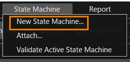
1. Select \[ State Machines &gt; New State Machine \] from the menu bar.
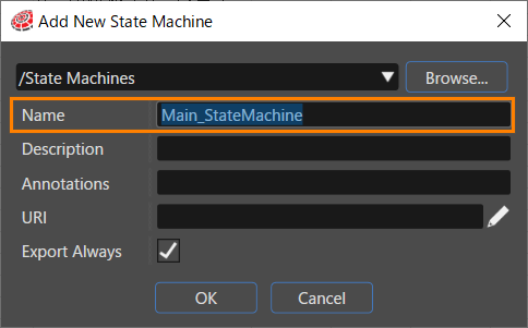
- The \[ New State Machine \] dialog will appear.  
    <div drawio-diagram="8097"><img src="https://doc316en.candera.eu/uploads/images/drawio/2025-03/drawing-4-1742280430.png" alt=""/></div>

3. Click \[ Browse \] at the top of the dialog.
- The \[ Select Location \] dialog will appear.

5. Select StateMachines and click \[ OK \].
- The location “/State Machines” is selected as the save location for the new State Machine.

7. Set \[ Name \] in the dialog to "Main\_StateMachine" and click the \[ OK \] button.
- The Main\_StateMachine is newly created in the \[ State Machines \] folder in the Solution Explorer.  
    <div drawio-diagram="8098"><img src="https://doc316en.candera.eu/uploads/images/drawio/2025-03/drawing-4-1742280486.png" alt=""/></div>


#### Setting the Global State Machine  


1. Select the Main\_StateMachine in the \[ State Machines \] folder in the Solution Explorer.
- The Main\_StateMachine properties will be displayed in the Properties panel.

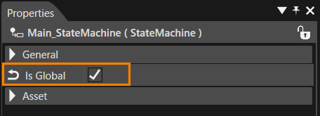
3. Enable the \[ Is Global \] checkbox in the \[ General \] category of the properties.
- The Main\_StateMachine will be set as a Global State Machine.  
    <div drawio-diagram="8099"><img src="https://doc316en.candera.eu/uploads/images/drawio/2025-03/drawing-4-1742280545.png" alt=""/></div>


<p class="callout info">For details on the functions of the Global State Machine, please refer to <span style="color: rgb(230, 126, 35);">[this page](https://doc316en.candera.eu/link/203#bkmrk-globalstatemachine-%E3%81%AE)</span>.</p>

### Basic Structure

Using the Main\_StateMachine we created earlier, we will add a State to configure the initial state of the Main Menu scene, and then set the appropriate rendering settings. In addition, when the Main Menu State is entered, the Main Menu scene will be activated, and the Clear and Swap scenes will also be activated so that they are rendered correctly.

#### Initial State and State Addition for Main Menu

1. Double-click on the Main\_StateMachine in the \[ State Machines \] folder in the Solution Explorer.
- The **State Machine Editor** panel will be displayed.
- There is already an Initial State and one State.

3. Select the State on the State Machine Editor.
- The properties of the selected State will be displayed in the Properties Panel.

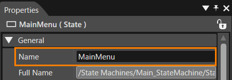
5. Change the \[ Name \] in the \[ General \] category of the Properties Panel to MainMenu.
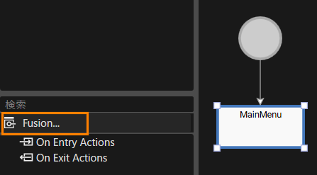
- The State name on the State Machine Editor will change to MainMenu.  
    <div drawio-diagram="8100"><img src="https://doc316en.candera.eu/uploads/images/drawio/2025-03/drawing-4-1742280601.png" alt=""/></div>


#### Adding an OnEntry Action  


1. With the MainMenu State selected, click \[ Fusion \] at the bottom left of the State Machine Editor panel.
- The Fusion panel for the MainMenu State will be displayed.  
    <div drawio-diagram="8101"><img src="https://doc316en.candera.eu/uploads/images/drawio/2025-03/drawing-4-1742280622.png" alt=""/></div>

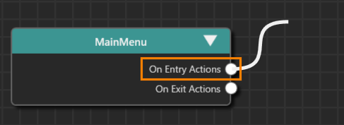
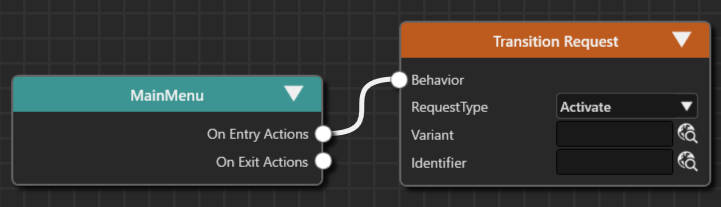
3. Drag the \[ On Entry Actions \] connector on the right of the MainMenu Fusion node and move the mouse.  
    <div drawio-diagram="8102"><img src="https://doc316en.candera.eu/uploads/images/drawio/2025-03/drawing-4-1742280643.png" alt=""/></div>
4. A link will appear as you move the mouse, so release the left mouse button at the any location.
- The \[ Select Behavior \] dialog will be displayed.
- The selectable behaviors will be displayed by category.

6. Select “Action &gt; Transition &gt; Transition Request” from the list and connect it to the top node.
- You can also narrow down the list of behaviors in the dialog by entering “Transition Request” in the search field at the top of the dialog.
- Transition Request is connected to MainMenu.
- The default Activate is selected for the \[RequestType\] of Transition Request.  
    <div drawio-diagram="8103"><img src="https://doc316en.candera.eu/uploads/images/drawio/2025-03/drawing-4-1742280666.png" alt=""/></div>

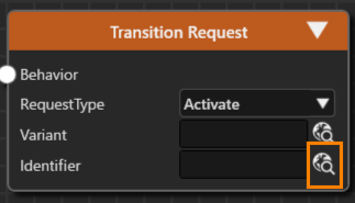
8. Press the select item button to the right of the \[ Identifier \] of the Transition Request.
- The \[ Choose Item \] dialog box will appear.  
    <div drawio-diagram="8104"><img src="https://doc316en.candera.eu/uploads/images/drawio/2025-03/drawing-4-1742280681.png" alt=""/></div>

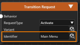
10. Select \[ Scenes &gt; Main Menu \] from the left window.
- The Main Menu you selected will be registered in the \[ Identifier \] of the Transition Request.  
    <div drawio-diagram="8105"><img src="https://doc316en.candera.eu/uploads/images/drawio/2025-03/drawing-4-1742280701.png" alt=""/></div>

12. Select the Transition Request Fusion node you set up, and execute \[ Close \] from the context menu.
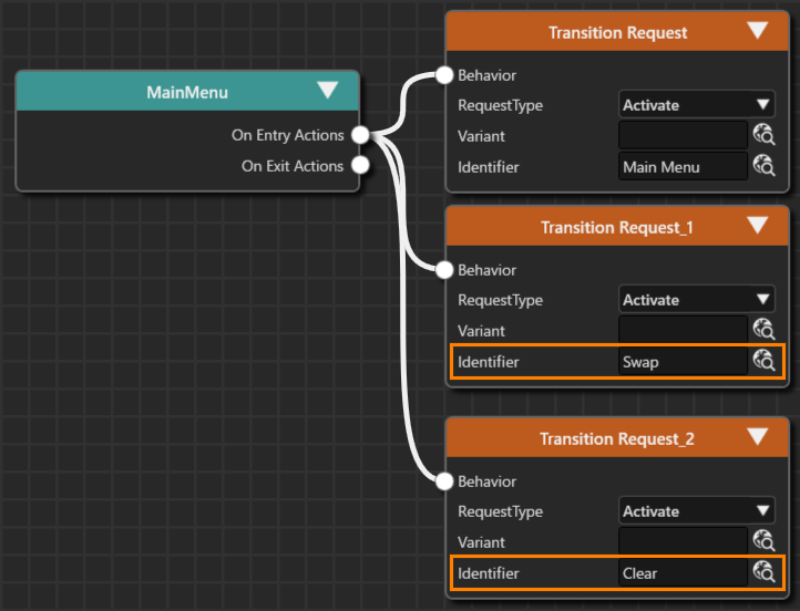
13. On the \[ Clone Item \] dialog, select the \[ Multiple Clone \] tab, specify 2 for \[ Number of Copies \] and click the \[ OK \] button.
- The duplicated Fusion nodes overlap, so move them using the mouse.
- The Fusion nodes named Transition Request\_1 and Transition Request\_2 are connected to the MainMenu Fusion node.
- The \[ RequestType \] of each Fusion node is set to the default Activate.

15. For the \[ Identifier \] of the added Transition Request Fusion nodes, select the **Swap** and **Clear** scenes respectively.  
    <div drawio-diagram="8106"><img src="https://doc316en.candera.eu/uploads/images/drawio/2025-03/drawing-4-1742280721.png" alt=""/></div>

This completes the settings for the OnEntry action for the MainMenu State. When you transition to the MainMenu State, the Clear and Swap scenes will be activated in addition to the Main Menu scene, so things like clearing the render will be executed at the same time.

### Main Menu State Structure

#### Adding a State  


1. Double-click on Main\_StateMachine in the \[ State Machines \] folder in the Solution Explorer.
- The State Machine Editor will appear.

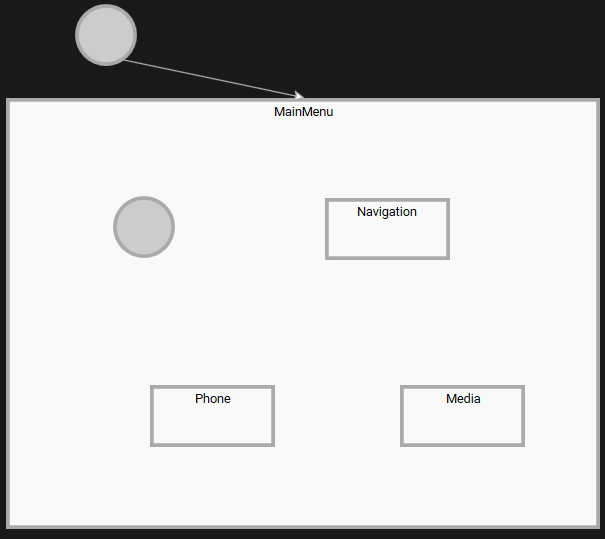
3. After selecting the MainMenu State, drag the resizing handles displayed in the four corners of the state with the mouse to expand the size of the MainMenu State.
4. Place one Initial State and three States in the MainMenu State from the toolbar at the top right of the State Machine Editor.
5. Change the names of the three added States to Navigation, Phone and Media respectively.
- For instructions on how to change State names, please refer to [here](#bkmrk-initial-state-and-st).  
    <div drawio-diagram="8107"><img src="https://doc316en.candera.eu/uploads/images/drawio/2025-03/drawing-4-1742280742.png" alt=""/></div>


#### OnEntry/OnExit settings

When transitioning to each State (entering and exiting States), it is necessary to activate and deactivate the corresponding scenes. In addition, when each scene is activated or deactivated, it is necessary to set the Main Menu scene text to be displayed or hidden in conjunction with this.

##### Scene display settings  


1. With the Navigation State selected, click \[ Fusion \] in the lower left of the State Machine Editor panel.
- The Fusion panel for the Navigation State will be displayed.

3. Drag the \[ On Entry Actions \] connector on the right of the Navigation Fusion node and move the mouse.
4. A link will appear as you move the mouse, so release the left mouse button at the any location.
- The \[ Select Behavior \] dialog will be displayed.
- The selectable behaviors will be displayed by category.

6. Select “Action &gt; Transition &gt; Transition Request” from the list and connect it to the top node.
- You can also narrow down the list of behaviors in the dialog by entering “Transition Request” in the search field at the top of the dialog.
- The Transition Request is connected to \[Navigation &gt; On Exit Actions\].

8. Repeat the same process for the \[On Exit Actions\] of the Navigation Fusion node to connect the Transition Request Fusion node.
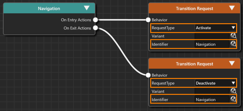
9. Make the following settings for the two Transition Requests that you have connected.  
    <div drawio-diagram="8108"><img src="https://doc316en.candera.eu/uploads/images/drawio/2025-03/drawing-4-1742280768.png" alt=""/></div>
    
      
    <table border="1" style="border-collapse: collapse; width: 51.6753%; height: 118.4px;"><colgroup><col style="width: 34.7326%;"></col><col style="width: 28.974%;"></col><col style="width: 36.4932%;"></col></colgroup><tbody><tr style="height: 29.6px;"><td rowspan="2" style="height: 59.2px; background-color: rgb(35, 111, 161);"><span style="color: rgb(255, 255, 255);">On Entry Actions</span></td><td style="height: 29.6px; background-color: rgb(194, 224, 244);">RequestType</td><td style="height: 29.6px;">Activate</td></tr><tr style="height: 29.6px;"><td style="height: 29.6px; background-color: rgb(194, 224, 244);">Identifier</td><td style="height: 29.6px;">Navigation</td></tr><tr style="height: 29.6px;"><td rowspan="2" style="height: 59.2px; background-color: rgb(35, 111, 161);"><span style="color: rgb(255, 255, 255);">On Exit Actions</span></td><td style="height: 29.6px; background-color: rgb(194, 224, 244);">RequestType</td><td style="height: 29.6px;">Deactivate</td></tr><tr style="height: 29.6px;"><td style="height: 29.6px; background-color: rgb(194, 224, 244);">Identifier</td><td style="height: 29.6px;">Navigation</td></tr></tbody></table>
10. Repeat the same procedure to make similar settings for Phone and Media State.  
    <table border="1" style="border-collapse: collapse; width: 51.6753%; height: 118.4px;"><colgroup><col style="width: 34.7326%;"></col><col style="width: 28.9855%;"></col><col style="width: 36.4818%;"></col></colgroup><tbody><tr><td class="align-center" colspan="3" style="background-color: rgb(0, 0, 0);">**<span style="color: #ffffff;">Phone State</span>**</td></tr><tr style="height: 29.6px;"><td rowspan="2" style="height: 59.2px; background-color: rgb(35, 111, 161);"><span style="color: rgb(255, 255, 255);">On Entry Actions</span></td><td style="height: 29.6px; background-color: rgb(194, 224, 244);">RequestType</td><td style="height: 29.6px;">Activate</td></tr><tr style="height: 29.6px;"><td style="height: 29.6px; background-color: rgb(194, 224, 244);">Identifier</td><td style="height: 29.6px;">Phone</td></tr><tr style="height: 29.6px;"><td rowspan="2" style="height: 59.2px; background-color: rgb(35, 111, 161);"><span style="color: rgb(255, 255, 255);">On Exit Actions</span></td><td style="height: 29.6px; background-color: rgb(194, 224, 244);">RequestType</td><td style="height: 29.6px;">Deactivate</td></tr><tr style="height: 29.6px;"><td style="height: 29.6px; background-color: rgb(194, 224, 244);">Identifier</td><td style="height: 29.6px;">Phone</td></tr><tr><td class="align-center" colspan="3" style="background-color: rgb(0, 0, 0);">**<span style="color: #ffffff;">Media State</span>**</td></tr><tr><td rowspan="2" style="height: 59.2px; background-color: rgb(35, 111, 161);"><span style="color: rgb(255, 255, 255);">On Entry Actions</span></td><td style="height: 29.6px; background-color: rgb(194, 224, 244);">RequestType</td><td style="height: 29.6px;">Activate</td></tr><tr><td style="height: 29.6px; background-color: rgb(194, 224, 244);">Identifier</td><td style="height: 29.6px;">Media Menu</td></tr><tr><td rowspan="2" style="height: 59.2px; background-color: rgb(35, 111, 161);"><span style="color: rgb(255, 255, 255);">On Exit Actions</span></td><td style="height: 29.6px; background-color: rgb(194, 224, 244);">RequestType</td><td style="height: 29.6px;">Deactivate</td></tr><tr><td style="height: 29.6px; background-color: rgb(194, 224, 244);">Identifier</td><td style="height: 29.6px;">Media Menu</td></tr></tbody></table>

##### Text Display Settings

1. With the Navigation State selected, click \[ Fusion \] at the bottom left of the State Machine Editor panel.
- The Fusion panel for the Navigation State will be displayed.

3. Drag the \[ On Entry Actions \] connector on the right of the Navigation Fusion node and move the mouse.
4. A link will appear as you move the mouse, so release the left mouse button at the any location.
- The 'Select Behavior' dialog will appear.
- The available behaviors will be displayed in categories.

6. Select "Action &gt; Property &gt; Enable Rendering" from the list and connect it to the top node.
- You can also narrow down the list of behaviors in the dialog by entering "Enable Rendering" in the search field at the top of the dialog.
- Enable Rendering is connected to \[Navigation &gt; On Exit Actions\].

8. Repeat the same process for the \[On Exit Actions\] of the Navigation Fusion node to connect the Enable Rendering Fusion node.
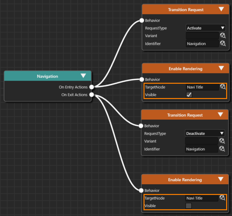
9. Make the following settings for the two Enable Renderings that have been connected.  
    <div drawio-diagram="8109"><img src="https://doc316en.candera.eu/uploads/images/drawio/2025-03/drawing-4-1742280800.png" alt=""/></div>
    
      
    <table border="1" style="border-collapse: collapse; width: 83.3763%; height: 118.4px;"><colgroup><col style="width: 21.2009%;"></col><col style="width: 17.3667%;"></col><col style="width: 61.2467%;"></col></colgroup><tbody><tr style="height: 29.6px;"><td rowspan="2" style="height: 29.6px; background-color: rgb(35, 111, 161);"><span style="color: rgb(255, 255, 255);">On Entry Actions</span></td><td style="height: 29.6px; background-color: rgb(194, 224, 244);">TargetNode</td><td style="height: 29.6px;">Scenes&gt;Main Menu&gt;OverlayLayout&gt;Navi Title</td></tr><tr style="height: 29.6px;"><td style="height: 29.6px; background-color: rgb(194, 224, 244);">Visible</td><td style="height: 29.6px;">Enable (check box selected)</td></tr><tr style="height: 29.6px;"><td rowspan="2" style="height: 29.6px; background-color: rgb(35, 111, 161);"><span style="color: rgb(255, 255, 255);">On Exit Actions</span></td><td style="height: 29.6px; background-color: rgb(194, 224, 244);">TargetNode</td><td style="height: 29.6px;">Scenes&gt;Main Menu&gt;OverlayLayout&gt;Navi Title</td></tr><tr style="height: 29.6px;"><td style="height: 29.6px; background-color: rgb(194, 224, 244);">Visible</td><td style="height: 29.6px;">Disable (uncheck)</td></tr></tbody></table>
10. Follow the same procedure to make similar settings for Phone State and Media State.   
    <table border="1" style="border-collapse: collapse; width: 83.3763%; height: 118.4px;"><colgroup><col style="width: 21.2009%;"></col><col style="width: 17.3321%;"></col><col style="width: 61.4361%;"></col></colgroup><tbody><tr><td class="align-center" colspan="3" style="background-color: rgb(0, 0, 0);"><span style="color: rgb(255, 255, 255);">**<span style="color: #ffffff;">Phone State</span>**</span></td></tr><tr style="height: 29.6px;"><td rowspan="2" style="height: 29.6px; background-color: rgb(35, 111, 161);"><span style="color: rgb(255, 255, 255);">On Entry Actions</span></td><td style="height: 29.6px; background-color: rgb(194, 224, 244);">TargetNode</td><td style="height: 29.6px;">Scenes&gt;Main Menu&gt;OverlayLayout&gt;Phone Title</td></tr><tr style="height: 29.6px;"><td style="height: 29.6px; background-color: rgb(194, 224, 244);">Visible</td><td style="height: 29.6px;">Enable</td></tr><tr style="height: 29.6px;"><td rowspan="2" style="height: 29.6px; background-color: rgb(35, 111, 161);"><span style="color: rgb(255, 255, 255);">On Exit Actions</span></td><td style="height: 29.6px; background-color: rgb(194, 224, 244);">TargetNode</td><td style="height: 29.6px;">Scenes&gt;Main Menu&gt;OverlayLayout&gt;Phone Title</td></tr><tr style="height: 29.6px;"><td style="height: 29.6px; background-color: rgb(194, 224, 244);">Visible</td><td style="height: 29.6px;">Disable</td></tr><tr><td class="align-center" colspan="3" style="background-color: rgb(0, 0, 0);"><span style="color: rgb(255, 255, 255);">**<span style="color: #ffffff;">Media State</span>**</span></td></tr><tr><td rowspan="2" style="height: 29.6px; background-color: rgb(35, 111, 161);"><span style="color: rgb(255, 255, 255);">On Entry Actions</span></td><td style="height: 29.6px; background-color: rgb(194, 224, 244);">TargetNode</td><td style="height: 29.6px;">Scenes&gt;Main Menu&gt;OverlayLayout&gt;Media Title</td></tr><tr><td style="height: 29.6px; background-color: rgb(194, 224, 244);">Visible</td><td style="height: 29.6px;">Enable</td></tr><tr><td rowspan="2" style="height: 29.6px; background-color: rgb(35, 111, 161);"><span style="color: rgb(255, 255, 255);">On Exit Actions</span></td><td style="height: 29.6px; background-color: rgb(194, 224, 244);">TargetNode</td><td style="height: 29.6px;">Scenes&gt;Main Menu&gt;OverlayLayout&gt;Media Title</td></tr><tr><td style="height: 29.6px; background-color: rgb(194, 224, 244);">Visible</td><td style="height: 29.6px;">Disable</td></tr></tbody></table>

#### Adding a Transition

We will now create a transition between the states we have created so far.

##### Setting the Initial State

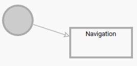
We will set the transition from the Initial State to the Navigation State, which is the initial state.

1. Double-click on Main\_StateMachine in the \[ State Machines \] folder in the Solution Explorer.
- The State Machine Editor will appear.

3. Drag and drop \[ Transition \] from the toolbar at the top of the panel to the Initial State in the MaiMenu State.
- The Transition will be connected to the Initial State, and it will be ready to be placed.

5. While the Transition is ready to be placed, click on the Navigation State.
- The Initial State and Navigation State will be connected by the Transition.
- The direction of the Transition connection is from the Initial State to the Navigation State.  
    <div drawio-diagram="8110"><img src="https://doc316en.candera.eu/uploads/images/drawio/2025-03/drawing-4-1742280823.png" alt=""/></div>


With this setting, the transition to the Navigation State has been configured as the initial state of the MainMenu State.

##### Transition settings between each State

Next, we will set up the transitions between each State (Navigation, Phone, Media).

1. From the toolbar at the top right of the State Machine Editor, drag the Transition and drop it onto the Navigation State (the starting side of the transition).   
    
    - The Transition (arrow) will appear on the State Machine Editor and be ready to be dragged.
2. Extend the Transition (arrow) to the Media State (end of transition) and click.  
    
    - The two states, Navigation and Media, will be connected by an arrow.
3. With the added Transition selected, click \[ Fusion... \] at the bottom left of the State Machine Editor panel.   
    
    - The Fusion panel will open, and the Fusion diagram for the Transition will be displayed.
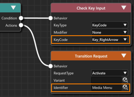
    - The Check Click Fusion node is connected to the connector (Condition) at the top right of the Transition Fusion node.
4. Select the Check Click Fusion node that is connected by default, and press the Delete key. 
    - The Check Click Fusion node will be deleted.
5. Drag the connector (Condition) at the upper right of the Transition Fusion node, move the mouse, and release the left mouse button at the any location. 
    - The \[Select Behavior\] dialog will open.
6. Enter “Check Key Input” in the search field at the top of the dialog.   
    
    - The list of behaviors in the dialog will be narrowed down, and Condition &gt; Input &gt; Check Key Input will be displayed.
7. Double-click Check Key Input. 
    - The Check Key Input Fusion node will be linked to the Condition connector of the Transition Fusion node.
8. Drag the connector (Actions) at the bottom right of the Transition Fusion node, move the mouse, and release the left mouse button at the any location. 
    - The \[Select Behavior\] dialog will open.
9. Enter “Transition Request” in the search field at the top of the dialog.   
    
    - The list of behaviors in the dialog will be narrowed down, and Action &gt; Transition &gt; Transition Request will be displayed.
10. Double-click Transition Request. 
    - The Transition Request Fusion node will be linked to the Actions connector of the Transition Fusion node.
11. Make the following settings for the Transition Request Fusion node.  
    <div drawio-diagram="8111"><img src="https://doc316en.candera.eu/uploads/images/drawio/2025-03/drawing-4-1742280855.png" alt=""/></div>


    - Clicking the upward-pointing arrow icon in the upper right of the Fusion panel will switch the display to the State.  
        <table border="1" class="align-left" id="bkmrk-items-setting-value--0" style="border-collapse: collapse; width: 393px; height: 89.3907px; border-width: 1px;"><colgroup><col style="width: 197px;"></col><col style="width: 197px;"></col></colgroup><tbody><tr><td class="align-center" colspan="2" style="border-width: 1px; background-color: rgb(0, 0, 0);"><span style="color: rgb(255, 255, 255);">**<span style="vertical-align: inherit;"><span style="vertical-align: inherit;">Check Key Input</span></span>**</span></td></tr><tr><td style="border-width: 1px; background-color: rgb(35, 111, 161);"><span style="vertical-align: inherit; color: rgb(255, 255, 255);"><span style="vertical-align: inherit;">KeyCode</span></span></td><td style="border-width: 1px;"><span style="vertical-align: inherit;"><span style="vertical-align: inherit;">Key\_RightArrow</span></span></td></tr><tr><td class="align-center" colspan="2" style="border-width: 1px; background-color: rgb(0, 0, 0);"><span style="color: rgb(255, 255, 255);">**<span style="vertical-align: inherit;"><span style="vertical-align: inherit;">Transition Request</span></span>**</span></td></tr><tr style="height: 29.7969px;"><td style="border-width: 1px; height: 29.7969px; background-color: rgb(35, 111, 161);"><span style="vertical-align: inherit; color: rgb(255, 255, 255);"><span style="vertical-align: inherit;">RequestType</span></span></td><td style="border-width: 1px; height: 29.7969px;"><span style="vertical-align: inherit;"><span style="vertical-align: inherit;">Activate</span></span></td></tr><tr style="height: 29.7969px;"><td style="border-width: 1px; height: 29.7969px; background-color: rgb(35, 111, 161);"><span style="vertical-align: inherit; color: rgb(255, 255, 255);"><span style="vertical-align: inherit;">Identifier</span></span></td><td style="border-width: 1px; height: 29.7969px;"><span style="vertical-align: inherit;"><span style="vertical-align: inherit;">Scenes＞Media Menu</span></span></td></tr></tbody></table>
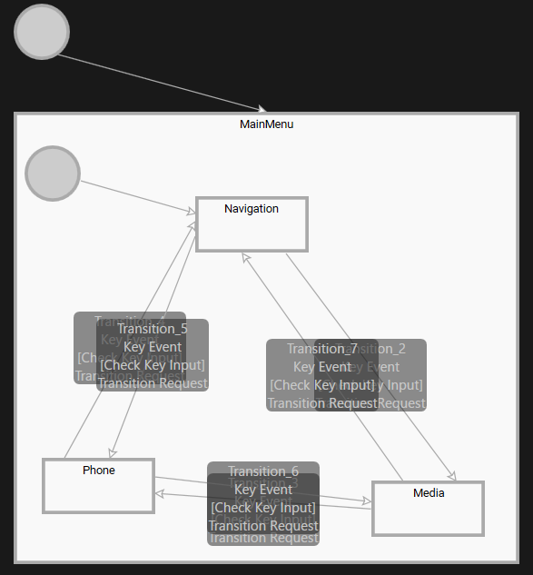
12. Repeat the above steps 1 to 11 to set the following five transitions. 
    - The RequestType for all of these is Activate (default).  
        <table border="1" class="align-left" style="border-collapse: collapse; width: 610px; border-width: 1px;"><colgroup><col style="width: 168px;"></col><col style="width: 215px;"></col><col style="width: 226px;"></col></colgroup><tbody><tr><td style="border-width: 1px; background-color: rgb(35, 111, 161);">**<span style="color: rgb(255, 255, 255);">Transition</span>**
        
        </td><td style="border-width: 1px; background-color: rgb(35, 111, 161);">**<span style="vertical-align: inherit; color: rgb(255, 255, 255);"><span style="vertical-align: inherit;"><span style="vertical-align: inherit; color: rgb(255, 255, 255);"><span style="vertical-align: inherit;">Check Key Input＞KeyCode</span></span></span></span>**</td><td style="border-width: 1px; background-color: rgb(35, 111, 161);">**<span style="vertical-align: inherit; color: rgb(255, 255, 255);"><span style="vertical-align: inherit;"><span style="vertical-align: inherit; color: rgb(255, 255, 255);"><span style="vertical-align: inherit;">Transition Request&gt;Identifier</span></span></span></span>**</td></tr><tr><td class="align-left" style="border-width: 1px;">Media to Phone</td><td rowspan="2" style="border-width: 1px;"><span style="vertical-align: inherit;"><span style="vertical-align: inherit;">  
        </span></span><span style="vertical-align: inherit;"><span style="vertical-align: inherit;">Key\_RightArrow</span></span></td><td class="align-left" style="border-width: 1px;"><span style="vertical-align: inherit;"><span style="vertical-align: inherit;">Scenes＞Phone</span></span></td></tr><tr><td class="align-left" style="border-width: 1px;">Phone to Navigation</td><td class="align-left" style="border-width: 1px;"><span style="vertical-align: inherit;"><span style="vertical-align: inherit;">Scenes＞Navigation</span></span></td></tr><tr><td class="align-left" style="border-width: 1px;">Navigation to Phone</td><td rowspan="3" style="border-width: 1px;"><span style="vertical-align: inherit;"><span style="vertical-align: inherit;">  
        </span></span>
        
        <span style="vertical-align: inherit;"><span style="vertical-align: inherit;">Key\_LeftArrow  
        </span></span><span style="vertical-align: inherit;"><span style="vertical-align: inherit;">  
        </span></span></td><td class="align-left" style="border-width: 1px;"><span style="vertical-align: inherit;"><span style="vertical-align: inherit;">Scenes＞Phone</span></span>
        
        </td></tr><tr><td class="align-left" style="border-width: 1px;">Phone to Media</td><td class="align-left" style="border-width: 1px;"><span style="vertical-align: inherit;"><span style="vertical-align: inherit;">Scenes＞Media Menu</span></span></td></tr><tr><td class="align-left" style="border-width: 1px;">Media to Navigation</td><td class="align-left" style="border-width: 1px;"><span style="vertical-align: inherit;"><span style="vertical-align: inherit;">Scenes＞Navigation</span></span></td></tr></tbody></table>
13. When all settings are complete, the screen will look like the one below.  
    <div drawio-diagram="8112"><img src="https://doc316en.candera.eu/uploads/images/drawio/2025-03/drawing-4-1742280883.png" alt=""/></div>

With the above settings, the scene that is displayed when a transition occurs from each scene has been set.

### Checking the transition state

Use the Player to check the transition between the states set in the previous section.

#### Starting the Player   


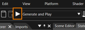
To start the Player, click the \[ Play selected scenario \] icon in the toolbar.

<div drawio-diagram="8113"><img src="https://doc316en.candera.eu/uploads/images/drawio/2025-03/drawing-4-1742280923.png" alt=""/></div>

If you have not saved the solution before performing this operation, a dialog box will appear prompting you to save the solution. In this case, click the \[ OK \] button in the dialog box. The asset file will be automatically generated and opened in the CGI Player.

#### Checking the screen transition

Use the Player to check the screen transition.

1. Click the \[ Play selected scenario \] icon on the toolbar to start the Player.
- Three windows will open, and you can see that the simulation display, one of the windows, displays the “Navi Title” and “Navigation” text, and that the initial transition has occurred to the Main Menu and Navigation scenes.

3. By pressing the left and right arrow keys on the keyboard, you can switch the text on the screen and see that you have transitioned to the specified scene.
4. Close the CGI Panel and exit the Player.
- All three windows that were open will close.

# Part 3: Subchart and History State

This page explains the procedure for setting up complex scene transitions using Subchart and History State in CGI Studio.

Media State is converted into a Subchart, and bidirectional transitions between the three sub-scenes—Radio, Bluetooth, and USB—are configured. Up and down key inputs (Key\_UpArrow/Key\_DownArrow) are used to switch scenes, and OnEntry/OnExit actions control the visibility of each scene. Additionally, to retain the previous selection state when returning to the Media scene after transitioning to another scene, the Initial State is replaced with a History State to track the media device state. Finally, scene transition operations are verified and simulated using the Player.

### Configure SubChart

The Media States that exist in Main\_StateMachine are configured as SubCharts. Within the Media States configured as SubCharts, the States for Radio, Bluetooth, and USB are placed.

#### Converting a Media State to a Subchart

1. Double-click on Main\_StateMachineSolution in the \[ State Machines \] folder in the Solution Explorer.
- The State Machine Editor will open and display the Main\_StateMachine diagram.

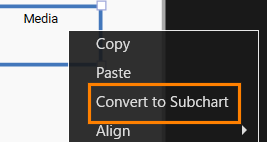
3. After selecting the Media State, select \[ Convert to Subchart \] from the context menu.
- The Media State will be converted to a Subchart (the “S” indicating that it is a Subchart will be displayed in the lower right of the State).  
    <div drawio-diagram="8096"><img src="https://doc316en.candera.eu/uploads/images/drawio/2025-03/drawing-4-1742280362.png" alt=""/></div>


The operation to convert Media State to SubChart is now complete.

- To move to the SubChart, select Media State and double-click.
- To return to the original State Diagram from the SubChart, use the \[Hierarchy Navigation Button\] in the State/Transition view screen in the upper right of the State Machine Editor panel.

#### Adding an Initial State and States

1. Double-click on the Main\_StateMachine in the \[ State Machines \] folder in the Solution Explorer.   
    
    - The **State Machine Editor** panel will be displayed.
2. After selecting the Media State, double-click to move it into the SubChart. 
    - As this is immediately after the SubChart conversion, only the Subchart frame will be displayed.
3. Expand the size of the Subchart by dragging the Subchart frame handle with the mouse. 
    - Expand it to a sufficient size to add the Initial State and States.
4. In the Subchart, place one Initial State and three States from the toolbar at the top right of the State Machine Editor.
5. Change the names of the three States you added to Radio, Bluetooth, and USB, respectively.

The placement of the basic components is now complete. Continue to configure the OnEntry action and Transition settings.

#### Structure of each State

When transitioning to each State in the Subchart (entering and exiting States), the corresponding scene must be made active or inactive. In addition, when each scene is made active or inactive, the Media Menu scene text must be set to be displayed or hidden accordingly.

##### Scene display settings  


1. With the Radio State selected, click \[ Fusion \] in the lower left of the State Machine Editor panel.
- The Fusion panel for the Radio State will be displayed.

3. Drag the \[ On Entry Actions \] connector on the right of the Radio Fusion node and move the mouse.
4. A link will appear as you move the mouse, so release the left mouse button at the any location.
- The \[ Select Behavior \] dialog will be displayed.
- The selectable behaviors will be displayed by category.

6. Select “Action &gt; Transition &gt; Transition Request” from the list and connect it to the top node.
- You can also narrow down the list of behaviors in the dialog by entering “Transition Request” in the search field at the top of the dialog.
- The Transition Request is connected to \[Radio &gt; On Exit Actions\].

8. Repeat the same process for the \[On Exit Actions\] of the Radio Fusion node to connect the Transition Request Fusion node.
9. Make the following settings for the two Transition Requests that you have connected.  
    <table border="1" style="border-collapse: collapse; width: 51.6753%; height: 118.4px;"><colgroup><col style="width: 34.7326%;"></col><col style="width: 28.974%;"></col><col style="width: 36.4932%;"></col></colgroup><tbody><tr style="height: 29.6px;"><td rowspan="2" style="height: 59.2px; background-color: rgb(35, 111, 161);"><span style="color: rgb(255, 255, 255);">On Entry Actions</span></td><td style="height: 29.6px; background-color: rgb(194, 224, 244);">RequestType</td><td style="height: 29.6px;">Activate</td></tr><tr style="height: 29.6px;"><td style="height: 29.6px; background-color: rgb(194, 224, 244);">Identifier</td><td style="height: 29.6px;">Media Radio scene</td></tr><tr style="height: 29.6px;"><td rowspan="2" style="height: 59.2px; background-color: rgb(35, 111, 161);"><span style="color: rgb(255, 255, 255);">On Exit Actions</span></td><td style="height: 29.6px; background-color: rgb(194, 224, 244);">RequestType</td><td style="height: 29.6px;">Deactivate</td></tr><tr style="height: 29.6px;"><td style="height: 29.6px; background-color: rgb(194, 224, 244);">Identifier</td><td style="height: 29.6px;">Media Radio scene</td></tr></tbody></table>
10. Repeat the same procedure to make similar settings for Bluetooth and USB State.  
    <table border="1" style="border-collapse: collapse; width: 56.5722%; height: 118.4px;"><colgroup><col style="width: 34.6874%;"></col><col style="width: 26.0209%;"></col><col style="width: 39.4743%;"></col></colgroup><tbody><tr><td class="align-center" colspan="3" style="background-color: rgb(0, 0, 0);">**<span style="color: #ffffff;">Phone State</span>**</td></tr><tr style="height: 29.6px;"><td rowspan="2" style="height: 59.2px; background-color: rgb(35, 111, 161);"><span style="color: rgb(255, 255, 255);">On Entry Actions</span></td><td style="height: 29.6px; background-color: rgb(194, 224, 244);">RequestType</td><td style="height: 29.6px;">Activate</td></tr><tr style="height: 29.6px;"><td style="height: 29.6px; background-color: rgb(194, 224, 244);">Identifier</td><td style="height: 29.6px;">Media Bluetooth scene</td></tr><tr style="height: 29.6px;"><td rowspan="2" style="height: 59.2px; background-color: rgb(35, 111, 161);"><span style="color: rgb(255, 255, 255);">On Exit Actions</span></td><td style="height: 29.6px; background-color: rgb(194, 224, 244);">RequestType</td><td style="height: 29.6px;">Deactivate</td></tr><tr style="height: 29.6px;"><td style="height: 29.6px; background-color: rgb(194, 224, 244);">Identifier</td><td style="height: 29.6px;">Media Bluetooth scene</td></tr><tr><td class="align-center" colspan="3" style="background-color: rgb(0, 0, 0);">**<span style="color: #ffffff;">Media State</span>**</td></tr><tr><td rowspan="2" style="height: 59.2px; background-color: rgb(35, 111, 161);"><span style="color: rgb(255, 255, 255);">On Entry Actions</span></td><td style="height: 29.6px; background-color: rgb(194, 224, 244);">RequestType</td><td style="height: 29.6px;">Activate</td></tr><tr><td style="height: 29.6px; background-color: rgb(194, 224, 244);">Identifier</td><td style="height: 29.6px;">Media USB scene</td></tr><tr><td rowspan="2" style="height: 59.2px; background-color: rgb(35, 111, 161);"><span style="color: rgb(255, 255, 255);">On Exit Actions</span></td><td style="height: 29.6px; background-color: rgb(194, 224, 244);">RequestType</td><td style="height: 29.6px;">Deactivate</td></tr><tr><td style="height: 29.6px; background-color: rgb(194, 224, 244);">Identifier</td><td style="height: 29.6px;">Media USB scene</td></tr></tbody></table>

##### Text Display Settings

1. With the Radio State selected, click \[ Fusion \] at the bottom left of the State Machine Editor panel.
- The Fusion panel for the Radio State will be displayed.

3. Drag the \[ On Entry Actions \] connector on the right of the Radio Fusion node and move the mouse.
4. A link will appear as you move the mouse, so release the left mouse button at the any location.
- The 'Select Behavior' dialog will appear.
- The available behaviors will be displayed in categories.

6. Select "Action &gt; Property &gt; Enable Rendering" from the list and connect it to the top node.
- You can also narrow down the list of behaviors in the dialog by entering "Enable Rendering" in the search field at the top of the dialog.
- Enable Rendering is connected to \[Radio &gt; On Exit Actions\].

8. Repeat the same process for the \[On Exit Actions\] of the Radio Fusion node to connect the Enable Rendering Fusion node.
9. Make the following settings for the two Enable Renderings that have been connected.  
    <table border="1" style="border-collapse: collapse; width: 83.3763%; height: 118.4px;"><colgroup><col style="width: 21.2009%;"></col><col style="width: 17.3667%;"></col><col style="width: 61.2467%;"></col></colgroup><tbody><tr style="height: 29.6px;"><td rowspan="2" style="height: 29.6px; background-color: rgb(35, 111, 161);"><span style="color: rgb(255, 255, 255);">On Entry Actions</span></td><td style="height: 29.6px; background-color: rgb(194, 224, 244);">TargetNode</td><td style="height: 29.6px;">Scenes&gt;Main Menu&gt;OverlayLayout&gt;Radio</td></tr><tr style="height: 29.6px;"><td style="height: 29.6px; background-color: rgb(194, 224, 244);">Visible</td><td style="height: 29.6px;">Enable (check box selected)</td></tr><tr style="height: 29.6px;"><td rowspan="2" style="height: 29.6px; background-color: rgb(35, 111, 161);"><span style="color: rgb(255, 255, 255);">On Exit Actions</span></td><td style="height: 29.6px; background-color: rgb(194, 224, 244);">TargetNode</td><td style="height: 29.6px;">Scenes&gt;Main Menu&gt;OverlayLayout&gt;Radio</td></tr><tr style="height: 29.6px;"><td style="height: 29.6px; background-color: rgb(194, 224, 244);">Visible</td><td style="height: 29.6px;">Disable (uncheck)</td></tr></tbody></table>
10. Follow the same procedure to make similar settings for Bluetooth and USB State.   
    <table border="1" style="border-collapse: collapse; width: 83.3763%; height: 118.4px;"><colgroup><col style="width: 21.2009%;"></col><col style="width: 17.3321%;"></col><col style="width: 61.4361%;"></col></colgroup><tbody><tr><td class="align-center" colspan="3" style="background-color: rgb(0, 0, 0);"><span style="color: rgb(255, 255, 255);">**<span style="color: #ffffff;">Phone State</span>**</span></td></tr><tr style="height: 29.6px;"><td rowspan="2" style="height: 29.6px; background-color: rgb(35, 111, 161);"><span style="color: rgb(255, 255, 255);">On Entry Actions</span></td><td style="height: 29.6px; background-color: rgb(194, 224, 244);">TargetNode</td><td style="height: 29.6px;">Scenes&gt;Main Menu&gt;OverlayLayout&gt;Bluetooth</td></tr><tr style="height: 29.6px;"><td style="height: 29.6px; background-color: rgb(194, 224, 244);">Visible</td><td style="height: 29.6px;">Enable</td></tr><tr style="height: 29.6px;"><td rowspan="2" style="height: 29.6px; background-color: rgb(35, 111, 161);"><span style="color: rgb(255, 255, 255);">On Exit Actions</span></td><td style="height: 29.6px; background-color: rgb(194, 224, 244);">TargetNode</td><td style="height: 29.6px;">Scenes&gt;Main Menu&gt;OverlayLayout&gt;Bluetooth</td></tr><tr style="height: 29.6px;"><td style="height: 29.6px; background-color: rgb(194, 224, 244);">Visible</td><td style="height: 29.6px;">Disable</td></tr><tr><td class="align-center" colspan="3" style="background-color: rgb(0, 0, 0);"><span style="color: rgb(255, 255, 255);">**<span style="color: #ffffff;">Media State</span>**</span></td></tr><tr><td rowspan="2" style="height: 29.6px; background-color: rgb(35, 111, 161);"><span style="color: rgb(255, 255, 255);">On Entry Actions</span></td><td style="height: 29.6px; background-color: rgb(194, 224, 244);">TargetNode</td><td style="height: 29.6px;">Scenes&gt;Main Menu&gt;OverlayLayout&gt;USB</td></tr><tr><td style="height: 29.6px; background-color: rgb(194, 224, 244);">Visible</td><td style="height: 29.6px;">Enable</td></tr><tr><td rowspan="2" style="height: 29.6px; background-color: rgb(35, 111, 161);"><span style="color: rgb(255, 255, 255);">On Exit Actions</span></td><td style="height: 29.6px; background-color: rgb(194, 224, 244);">TargetNode</td><td style="height: 29.6px;">Scenes&gt;Main Menu&gt;OverlayLayout&gt;USB</td></tr><tr><td style="height: 29.6px; background-color: rgb(194, 224, 244);">Visible</td><td style="height: 29.6px;">Disable</td></tr></tbody></table>

#### Adding a Transition

We will now create a transition between the states we have created so far.

##### Setting the Initial State

We will set the transition from the Initial State to the Radio State, which is the initial state.

1. Double-click on Main\_StateMachine in the \[ State Machines \] folder in the Solution Explorer.
- The State Machine Editor will appear.

3. After selecting Media State, double-click on it and move it into the SubChart.
4. Drag and drop \[ Transition \] from the toolbar at the top of the panel to the Initial State in the Subchart.
- The Transition will be connected to the Initial State, and it will be ready to be placed.

6. While the Transition is ready to be placed, click on the Radio State.
- The Initial State and Radio State will be connected by the Transition.
- The direction of the Transition connection is from the Initial State to the Radio State.


With this setting, the transition to the Radio State has been configured as the initial state of the Media State (Subchart).

##### Transition settings between each State

Next, we will set up the transitions between each State (Radio, Bluetooth, USB).

1. From the toolbar at the top right of the State Machine Editor, drag the Transition and drop it onto the Radio State (the starting side of the transition).   
    
    - The Transition (arrow) will appear on the State Machine Editor and be ready to be dragged.
2. Extend the Transition (arrow) to the Bluetooth State (end of transition) and click.  
    
    - The two states, Radio and Bluetooth, will be connected by an arrow.
3. With the added Transition selected, click \[ Fusion... \] at the bottom left of the State Machine Editor panel.   
    
    - The Fusion panel will open, and the Fusion diagram for the Transition will be displayed.
    - The Check Click Fusion node is connected to the connector (Condition) at the top right of the Transition Fusion node.
4. Select the Check Click Fusion node that is connected by default, and press the Delete key. 
    - The Check Click Fusion node will be deleted.
5. Drag the connector (Condition) at the upper right of the Transition Fusion node, move the mouse, and release the left mouse button at the any location. 
    - The \[Select Behavior\] dialog will open.
6. Enter “Check Key Input” in the search field at the top of the dialog.   
    
    - The list of behaviors in the dialog will be narrowed down, and Condition &gt; Input &gt; Check Key Input will be displayed.
7. Double-click Check Key Input. 
    - The Check Key Input Fusion node will be linked to the Condition connector of the Transition Fusion node.
8. Drag the connector (Actions) at the bottom right of the Transition Fusion node, move the mouse, and release the left mouse button at the any location. 
    - The \[Select Behavior\] dialog will open.
9. Enter “Transition Request” in the search field at the top of the dialog.   
    
    - The list of behaviors in the dialog will be narrowed down, and Action &gt; Transition &gt; Transition Request will be displayed.
10. Double-click Transition Request. 
    - The Transition Request Fusion node will be linked to the Actions connector of the Transition Fusion node.
11. Make the following settings for the Transition Request Fusion node.   
    
    - Clicking the upward-pointing arrow icon in the upper right of the Fusion panel will switch the display to the State.  
        <table border="1" class="align-left" id="bkmrk-items-setting-value--0" style="border-collapse: collapse; width: 393px; height: 89.3907px; border-width: 1px;"><colgroup><col style="width: 197px;"></col><col style="width: 197px;"></col></colgroup><tbody><tr><td class="align-center" colspan="2" style="border-width: 1px; background-color: rgb(0, 0, 0);"><span style="color: rgb(255, 255, 255);">**<span style="vertical-align: inherit;"><span style="vertical-align: inherit;">Check Key Input</span></span>**</span></td></tr><tr><td style="border-width: 1px; background-color: rgb(35, 111, 161);"><span style="vertical-align: inherit; color: rgb(255, 255, 255);"><span style="vertical-align: inherit;">KeyCode</span></span></td><td style="border-width: 1px;"><span style="vertical-align: inherit;"><span style="vertical-align: inherit;">Key\_DownArrow</span></span></td></tr><tr><td class="align-center" colspan="2" style="border-width: 1px; background-color: rgb(0, 0, 0);"><span style="color: rgb(255, 255, 255);">**<span style="vertical-align: inherit;"><span style="vertical-align: inherit;">Transition Request</span></span>**</span></td></tr><tr style="height: 29.7969px;"><td style="border-width: 1px; height: 29.7969px; background-color: rgb(35, 111, 161);"><span style="vertical-align: inherit; color: rgb(255, 255, 255);"><span style="vertical-align: inherit;">RequestType</span></span></td><td style="border-width: 1px; height: 29.7969px;"><span style="vertical-align: inherit;"><span style="vertical-align: inherit;">Activate</span></span></td></tr><tr style="height: 29.7969px;"><td style="border-width: 1px; height: 29.7969px; background-color: rgb(35, 111, 161);"><span style="vertical-align: inherit; color: rgb(255, 255, 255);"><span style="vertical-align: inherit;">Identifier</span></span></td><td style="border-width: 1px; height: 29.7969px;"><span style="vertical-align: inherit;"><span style="vertical-align: inherit;">Scenes＞Media Bluetooth</span></span></td></tr></tbody></table>
12. Repeat the above steps 1 to 11 to set the following five transitions. 
    - The RequestType for all of these is Activate (default).  
        <table border="1" class="align-left" style="border-collapse: collapse; width: 610px; border-width: 1px; height: 177.6px;"><colgroup><col style="width: 168px;"></col><col style="width: 215px;"></col><col style="width: 226px;"></col></colgroup><tbody><tr style="height: 29.6px;"><td style="border-width: 1px; background-color: rgb(35, 111, 161); height: 29.6px;">**<span style="color: rgb(255, 255, 255);">Transition</span>**
        
        </td><td style="border-width: 1px; background-color: rgb(35, 111, 161); height: 29.6px;">**<span style="vertical-align: inherit; color: rgb(255, 255, 255);"><span style="vertical-align: inherit;"><span style="vertical-align: inherit; color: rgb(255, 255, 255);"><span style="vertical-align: inherit;">Check Key Input＞KeyCode</span></span></span></span>**</td><td style="border-width: 1px; background-color: rgb(35, 111, 161); height: 29.6px;">**<span style="vertical-align: inherit; color: rgb(255, 255, 255);"><span style="vertical-align: inherit;"><span style="vertical-align: inherit; color: rgb(255, 255, 255);"><span style="vertical-align: inherit;">Transition Request&gt;Identifier</span></span></span></span>**</td></tr><tr style="height: 29.6px;"><td class="align-left" style="border-width: 1px; height: 29.6px;">Bluetooth to USB</td><td rowspan="2" style="border-width: 1px; height: 59.2px;"><span style="vertical-align: inherit;"><span style="vertical-align: inherit;">  
        </span></span><span style="vertical-align: inherit;"><span style="vertical-align: inherit;">Key\_DownArrow</span></span></td><td class="align-left" style="border-width: 1px; height: 29.6px;"><span style="vertical-align: inherit;"><span style="vertical-align: inherit;">Scenes＞Media USB</span></span></td></tr><tr style="height: 29.6px;"><td class="align-left" style="border-width: 1px; height: 29.6px;">USB to Radio</td><td class="align-left" style="border-width: 1px; height: 29.6px;"><span style="vertical-align: inherit;"><span style="vertical-align: inherit;">Scenes＞Media Radio</span></span></td></tr><tr style="height: 29.6px;"><td class="align-left" style="border-width: 1px; height: 29.6px;">Radio to USB</td><td rowspan="3" style="border-width: 1px; height: 88.8px;"><span style="vertical-align: inherit;"><span style="vertical-align: inherit;">  
        </span></span>
        
        <span style="vertical-align: inherit;"><span style="vertical-align: inherit;">Key\_UpArrow  
        </span></span><span style="vertical-align: inherit;"><span style="vertical-align: inherit;">  
        </span></span></td><td class="align-left" style="border-width: 1px; height: 29.6px;"><span style="vertical-align: inherit;"><span style="vertical-align: inherit;">Scenes＞Media USB</span></span>
        
        </td></tr><tr style="height: 29.6px;"><td class="align-left" style="border-width: 1px; height: 29.6px;">USB to Bluetooth</td><td class="align-left" style="border-width: 1px; height: 29.6px;"><span style="vertical-align: inherit;"><span style="vertical-align: inherit;">Scenes＞Media Bluetooth</span></span></td></tr><tr style="height: 29.6px;"><td class="align-left" style="border-width: 1px; height: 29.6px;">Bluetooth to Radio</td><td class="align-left" style="border-width: 1px; height: 29.6px;"><span style="vertical-align: inherit;"><span style="vertical-align: inherit;">Scenes＞Media Radio</span></span></td></tr></tbody></table>
13. When all settings are complete, the screen will look like the one below.  
    <div drawio-diagram="8094"><img src="https://doc316en.candera.eu/uploads/images/drawio/2025-03/drawing-4-1742280223.png" alt=""/></div>

With the above settings, the scene that is displayed when a transition occurs from each scene in the subchart has been set.


#### Checking the screen transition

Use the Player to check the screen transition.

1. Click the \[ Play selected scenario \] icon on the toolbar to start the Player.
- Three windows will open, and you can see that the simulation display, one of the windows, displays the “Navi Title” and “Navigation” text, and that the initial transition has occurred to the Main Menu and Navigation scenes.

3. Pressing the right arrow key on the keyboard switches the text on the screen, and “Media Title”, “Radio Title”, and “Radio” are displayed in the simulation display, and the transition to the Media Menu scene (Subchart) is performed.
4. Pressing the up and down arrow keys on the keyboard switches the text on the screen, and the transition to the “Radio”, “Bluetooth”, and “USB” scenes in the Subchart is performed sequentially.
5. Close the CGI Panel and exit the Player.
- All three windows that were open will close.


In addition to the switching between the Navigation, Phone and Media scenes set in Part 2, we were able to confirm that it is also possible to switch between the Radio, Bluetooth and USB scenes, which are subcharts. However, at present, even if you switch to a scene placed in a subchart in the Media scene, when you transition back to the Navigation or Phone scene (using the left and right directional keys) and then return to the Media scene, the Radio scene, which is always set as the initial scene of the Media scene, will be displayed.

If you want to display the scene that was displayed immediately before, you can do this by placing a History State in the Subchart.

### Configure History State

#### Placing the History State

1. Double-click on Main\_StateMachine in the \[ State Machines \] folder in the Solution Explorer.
- The State Machine Editor will appear.

3. After selecting the Media State, double-click to move it into the SubChart.
4. Select the Initial State in the Subchart and press the Delete key.
- The Initial State in the Subchart will be deleted.

6. Drag and drop \[ History State \] from the toolbar at the top of the panel into the Subchart.
- The History State will be placed in the Subchart.

8. Drag and drop \[Transition\] from the toolbar at the top of the panel into the Subchart.
- The Transition will be connected to the Initial State, and it will be ready to be placed.

10. While the Transition is ready to be placed, click on the Radio State.
- The History State and Radio State will be connected by the Transition.  
    <div drawio-diagram="8095"><img src="https://doc316en.candera.eu/uploads/images/drawio/2025-03/drawing-4-1742280290.png" alt=""/></div>


#### Checking the screen transition

Use the Player to check the screen transition.

1. Press the \[Play selected scenario...\] icon on the toolbar to start the Player.
- Three windows will open, and you can see that the simulation display shows “Navi Title” and “Navigation” text, and that the initial transition has occurred to the Main Menu and Navigation scenes.

3. Press the right arrow key on the keyboard once.
- The text “Media Title”, “Radio Title” and “Radio” will appear, and you will be taken to the Media Menu scene (Subchart).

5. Press the down arrow key on the keyboard once.
- The text on the screen will change, and “Bluetooth Title” and “Bluetooth” will appear.

7. Press the right arrow key on the keyboard once, and then press the left arrow key once.
- On the simulation display, “Phone Title” will be displayed, and then “Media Title” will be displayed again.
- In this case, “Bluetooth” will be displayed.

9. Close the CGI Panel and exit the Player.
- All three windows that were open will close.


By replacing the Initial State in the Subchart with the History State, you can see that the scene transition in the Subchart has become a state that remembers the state of the previous transition.

# Part 4: Add an Incoming Call

This page explains the procedure for adding an Incoming Call scene and configuring the state machine to display the scene with the Enter key and hide it with the ESC key in CGI Studio.

The existing Phone scene is duplicated to create the IncomingCall scene, and the background is customized by placing a SolidColorNode. A new Global State Machine (IncomingCall\_StateMachine) is created, and transitions between the CallInactive and CallActive states are configured. Conditions are set for transitioning to CallActive (displaying the call) with the Enter key and to CallInactive (hiding the call) with the ESC key. OnEntry/OnExit actions are used to control the activation and deactivation of the IncomingCall scene. Finally, screen transition operations are verified using the Player.

### Creatig the IncomingCall scene

#### Configure the IncomingCall Scene

The IncomingCall scene is created by duplicating the Phone scene.

1. In **\[Solution Explorer\]**, select **\[Scenes &gt; Phone\]**, then choose **\[Clone\]** from the context menu.
    
    
    - The **\[Clone Item\]** dialog will appear.
2. In the **\[Clone Item\]** dialog, select **\[Single Clone\]**, rename **\[Name\]** to **"IncomingCall"**, then click **\[OK\]**.
    
    
    - The **IncomingCall** scene will be created.
    - The scene tree will display the newly created **IncomingCall** scene.
3. Select the text node in the **IncomingCall** scene tree, then update **\[Text\]** in the **\[Properties\]** panel under **\[2D Text Node\]** to **"Incoming Call"**.
    
    
    - The text displayed in the Scene Editor will change to "Incoming Call".
4. To change the position of the text node on the Scene Editor, change the \[Transform\] setting in the text node's properties panel to the following.
    
    <table border="1" class="align-left" style="border-collapse: collapse; border-width: 1px; width: 300px;"><colgroup><col style="width: 41.8121%;"></col><col style="width: 58.1125%;"></col></colgroup><tbody><tr><td style="background-color: rgb(35, 111, 161);"><span style="color: rgb(236, 240, 241);">Position X</span></td><td>28</td></tr><tr><td style="background-color: rgb(35, 111, 161);"><span style="color: rgb(236, 240, 241);">Position Y</span></td><td>220</td></tr></tbody></table>
5. Drag and drop a \[Solid Color Node\] from \[Node 2D\] in the \[Toolbox\] panel onto the TextNode in the \[IncomingCall\] scene tree.
    
    
    - The SolidColorNode will be placed on the scene tree.
    - By placing it above the TextNode on the scene tree, the added SolidColorNode can be used as the background for the TextNode.
    - If you are unable to place it below the TextNode, you can adjust its position by dragging and dropping it after placing it on the scene tree.
    - The node added to the scene tree by this operation will have its \[Position\] set to X=0, Y=0 automatically in the \[Transform\] section of the Properties panel.
6. To change the position of the SolidColorNode on the scene editor, change the \[Transform\] setting in the SolidColorNode's property panel to the following.  
    <table border="1" class="align-left" style="border-collapse: collapse; border-width: 1px; width: 300px;"><colgroup><col style="width: 41.8121%;"></col><col style="width: 58.1125%;"></col></colgroup><tbody><tr><td style="background-color: rgb(35, 111, 161);"><span style="color: rgb(236, 240, 241);">Position X</span></td><td>5</td></tr><tr><td style="background-color: rgb(35, 111, 161);"><span style="color: rgb(236, 240, 241);">Position Y</span></td><td>200</td></tr></tbody></table>
7. After selecting the SolidColorNode on the scene tree, select the SolidColorBrushBlend that appears in the extra scene tree.  
    
    - The properties of the SolidColorBrushBlend effect will be displayed in the Properties panel.
8. To change the color and size of the SolidColorNode, set the following items in the Properties panel as shown in the table below.  
    <table border="1" style="border-collapse: collapse; width: 42.0103%; height: 207.2px;"><colgroup><col style="width: 26.4453%;"></col><col style="width: 23.9852%;"></col><col style="width: 49.508%;"></col></colgroup><tbody><tr style="height: 29.6px;"><td class="align-center" colspan="3" style="background-color: rgb(35, 111, 161); height: 29.6px;"><span style="color: rgb(255, 255, 255);">**Effect**</span>
    
    </td></tr><tr style="height: 29.6px;"><td rowspan="4" style="height: 29.6px;">FillColor</td><td style="height: 29.6px;">Red
    
    </td><td style="height: 29.6px;">1.0
    
    </td></tr><tr style="height: 29.6px;"><td style="height: 29.6px;">Green
    
    </td><td style="height: 29.6px;">0.0
    
    </td></tr><tr style="height: 29.6px;"><td style="height: 29.6px;">Blue
    
    </td><td style="height: 29.6px;">0.0
    
    </td></tr><tr style="height: 29.6px;"><td style="height: 29.6px;">Alpha
    
    </td><td style="height: 29.6px;">1.0
    
    </td></tr><tr style="height: 29.6px;"><td rowspan="2" style="height: 29.6px;">Size</td><td style="height: 29.6px;">X</td><td style="height: 29.6px;">380</td></tr><tr style="height: 29.6px;"><td style="height: 29.6px;">Y</td><td style="height: 29.6px;">90</td></tr></tbody></table>

The settings for the Incoming Call scene are now complete.


#### Sequence Number Configuration

Set the rendering order for the new scene created in the previous section. In this case, we will set it to 4, so we will also change the rendering order of the Swap Scene Camera, which was originally set to 4.

1. In the Render Target panel, select IncomingCall/Camera. 
    - The properties of the IncomingCall camera will be displayed in the Properties panel.
2. In the Properties panel, change the value of \[Sequence Number\] in the \[Camera\] category to 4.
3. Next, select Swap\\Camera in the Render Target panel.
    
    
    - The properties of the Swap camera will be displayed in the Properties panel.
4. In the Properties panel, change the value of \[Sequence Number\] in the \[Camera\] category to 5.
    
    <div drawio-diagram="8093"><img src="https://doc316en.candera.eu/uploads/images/drawio/2025-03/drawing-4-1742280096.png" alt=""/></div>

####   


### Creating an IncomingCall State Machine

We will create and configure a new State Machine for the IncomingCall scene.

#### Creating a new State Machine

1. Select \[ State Machines &gt; New State Machine \] from the menu bar.
- The \[ New State Machine \] dialog will appear.

3. Click \[ Browse \] at the top of the dialog.
- The \[ Select Location \] dialog will appear.

5. Select StateMachines and click \[ OK \].
- The location “/State Machines” is selected as the save location for the new State Machine.

7. Set \[ Name \] in the dialog to "IncomingCall\_StateMachine" and click the \[ OK \] button.
- The IncomingCall\_StateMachine is newly created in the \[ State Machines \] folder in the Solution Explorer.  
    <div drawio-diagram="8092"><img src="https://doc316en.candera.eu/uploads/images/drawio/2025-03/drawing-4-1742280069.png" alt=""/></div>


#### Setting the Global State Machine  


1. Select the IncomingCall\_StateMachine in the \[ State Machines \] folder in the Solution Explorer.
- The IncomingCall\_StateMachine properties will be displayed in the Properties panel.

3. Enable the \[ Is Global \] checkbox in the \[ General \] category of the properties.
- The IncomingCall\_StateMachine will be set as a Global State Machine.


#### Adding a State  


1. Double-click on IncomingCall\_StateMachine in the \[ State Machines \] folder in the Solution Explorer. 
    - The State Machine Editor will appear.
    - There is already one Initial State and one State.
2. Select a State on the State Machine Editor.
    
    
    - The properties of the selected State will be displayed in the Properties Panel.
3. Change the \[Name\] in the \[General\] category of the Properties Panel to CallInactive.
    
    
    - The State name on the State Machine Editor will change to CallInactive.
4. Next, place a State from the toolbar at the top right of the State Machine Editor.
5. Change the names of the added States to CallInActive.
6. Drag and drop \[Transition\] from the toolbar at the top of the panel to the Initial State in IncomingCall\_State. 
    - Transition will be connected to the Initial State and become ready to be placed.
7. While Transition is ready to be placed, click on CallInactive State.  
    <div drawio-diagram="8091"><img src="https://doc316en.candera.eu/uploads/images/drawio/2025-03/drawing-4-1742280026.png" alt=""/></div>

#### OnEntry/OnExit settings

When transitioning to each State (entering and exiting States), it is necessary to activate and deactivate the corresponding scenes.

##### Scene display settings  


1. With the CallActive State selected, click \[ Fusion \] in the lower left of the State Machine Editor panel.
- The Fusion panel for the Navigation State will be displayed.

3. Drag the \[ On Entry Actions \] connector on the right of the CallActive Fusion node and move the mouse.
4. A link will appear as you move the mouse, so release the left mouse button at the any location.
- The \[ Select Behavior \] dialog will be displayed.
- The selectable behaviors will be displayed by category.

6. Select “Action &gt; Transition &gt; Transition Request” from the list and connect it to the top node.
- You can also narrow down the list of behaviors in the dialog by entering “Transition Request” in the search field at the top of the dialog.
- The Transition Request is connected to \[CallActive &gt; On Exit Actions\].

8. Repeat the same process for the \[On Exit Actions\] of the CallActive Fusion node to connect the Transition Request Fusion node.
9. Make the following settings for the two Transition Requests that you have connected.  
    <table border="1" style="border-collapse: collapse; width: 51.6753%; height: 118.4px;"><colgroup><col style="width: 34.7326%;"></col><col style="width: 28.974%;"></col><col style="width: 36.4932%;"></col></colgroup><tbody><tr style="height: 29.6px;"><td rowspan="2" style="height: 59.2px; background-color: rgb(35, 111, 161);"><span style="color: rgb(255, 255, 255);">On Entry Actions</span></td><td style="height: 29.6px; background-color: rgb(194, 224, 244);">RequestType</td><td style="height: 29.6px;">Activate</td></tr><tr style="height: 29.6px;"><td style="height: 29.6px; background-color: rgb(194, 224, 244);">Identifier</td><td style="height: 29.6px;">IncomingCall scene</td></tr><tr style="height: 29.6px;"><td rowspan="2" style="height: 59.2px; background-color: rgb(35, 111, 161);"><span style="color: rgb(255, 255, 255);">On Exit Actions</span></td><td style="height: 29.6px; background-color: rgb(194, 224, 244);">RequestType</td><td style="height: 29.6px;">Deactivate</td></tr><tr style="height: 29.6px;"><td style="height: 29.6px; background-color: rgb(194, 224, 244);">Identifier</td><td style="height: 29.6px;">IncomingCall scene</td></tr></tbody></table>

##### Transition settings between each State

Next, we will set up the transitions between each State (CallInactive and CallActive).

1. From the toolbar at the top right of the State Machine Editor, drag the Transition and drop it onto the CallInactive State (the starting side of the transition).   
    
    - The Transition (arrow) will appear on the State Machine Editor and be ready to be dragged.
2. Extend the Transition (arrow) to the CallActive State (end of transition) and click.  
    
    - The two states, CallInactive and CallActive, will be connected by an arrow.
3. With the added Transition selected, click \[ Fusion... \] at the bottom left of the State Machine Editor panel.   
    
    - The Fusion panel will open, and the Fusion diagram for the Transition will be displayed.
    - The Check Click Fusion node is connected to the connector (Condition) at the top right of the Transition Fusion node.
4. Select the Check Click Fusion node that is connected by default, and press the Delete key. 
    - The Check Click Fusion node will be deleted.
5. Drag the connector (Condition) at the upper right of the Transition Fusion node, move the mouse, and release the left mouse button at the any location. 
    - The \[Select Behavior\] dialog will open.
6. Enter “Check Key Input” in the search field at the top of the dialog.   
    
    - The list of behaviors in the dialog will be narrowed down, and Condition &gt; Input &gt; Check Key Input will be displayed.
7. Double-click Check Key Input. 
    - The Check Key Input Fusion node will be linked to the Condition connector of the Transition Fusion node.
8. Make the following settings for the Check Key Input Fusion node. 
    - Clicking the upward-pointing arrow icon in the upper right of the Fusion panel will switch the display to the State.  
        <table border="1" class="align-left" id="bkmrk-items-setting-value--0" style="border-collapse: collapse; width: 393px; height: 89.3907px; border-width: 1px;"><colgroup><col style="width: 197px;"></col><col style="width: 197px;"></col></colgroup><tbody><tr><td class="align-center" colspan="2" style="border-width: 1px; background-color: rgb(0, 0, 0);"><span style="color: rgb(255, 255, 255);">**<span style="vertical-align: inherit;"><span style="vertical-align: inherit;">Check Key Input</span></span>**</span></td></tr><tr><td style="border-width: 1px; background-color: rgb(35, 111, 161);"><span style="vertical-align: inherit; color: rgb(255, 255, 255);"><span style="vertical-align: inherit;">KeyCode</span></span></td><td style="border-width: 1px;"><span style="vertical-align: inherit;"><span style="vertical-align: inherit;">Key\_Enter</span></span></td></tr></tbody></table>
9. Repeat the above operations 1 to 8, this time connecting the Transition from CallActive State to CallInactive State, and set the Check Key Input Fusion as shown in the table below.   
    <table border="1" class="align-left" id="bkmrk-check-key-input-keyc" style="border-collapse: collapse; width: 393px; height: 89.3907px; border-width: 1px;"><colgroup><col style="width: 197px;"></col><col style="width: 197px;"></col></colgroup><tbody><tr><td class="align-center" colspan="2" style="border-width: 1px; background-color: rgb(0, 0, 0);"><span style="color: rgb(255, 255, 255);">**<span style="vertical-align: inherit;"><span style="vertical-align: inherit;">Check Key Input</span></span>**</span></td></tr><tr><td style="border-width: 1px; background-color: rgb(35, 111, 161);"><span style="vertical-align: inherit; color: rgb(255, 255, 255);"><span style="vertical-align: inherit;">KeyCode</span></span></td><td style="border-width: 1px;"><span style="vertical-align: inherit;"><span style="vertical-align: inherit;">Key\_ESC</span></span></td></tr></tbody></table>
10. When all settings are complete, the screen will look like the one below.   
    <div drawio-diagram="8090"><img src="https://doc316en.candera.eu/uploads/images/drawio/2025-03/drawing-4-1742279942.png" alt=""/></div>

### Checking the transition state

Use the Player to check the transition between the states set in the previous section.

<span style="color: rgb(34, 34, 34); font-family: var(--font-heading, var(--font-body)); font-size: 1.666em; font-weight: 400;">Checking the screen transition</span>

Use the Player to check the screen transition.

1. Click the \[ Play selected scenario \] icon on the toolbar to start the Player.  
    
    - Three windows will open, and you can see that the simulation display, one of the windows, displays the “Navi Title” and “Navigation” text, and that the initial transition has occurred to the Main Menu and Navigation scenes.
2. By pressing the **Enter key** on the keyboard, the text “Incoming Call” will appear on the screen. 
    - Using the left and right directional keys in this state will move the scene, but the “Incoming Call” text will remain displayed.
3. Pressing the **ESC key** on the keyboard hides the “Incoming Call” text displayed on the screen.
4. Close the CGI Panel and exit the Player. 
    - All three windows that were open will close.

# Part 5: Count Received Calls

This page explains the procedure for adding an incoming call count function and displaying the count on a text node in the Main Menu scene in CGI Studio.

A "Received Calls: %d" text node is added to the Main Menu scene, and the call count is updated as a relative value each time the IncomingCall\_StateMachine enters the CallActive state using the Send Value As Event behavior. Furthermore, the Value and Format String behaviors are connected to the Fusion node of the TextNode to format and dynamically display the counted incoming calls on the screen. Finally, the operation of displaying calls with the Enter key, hiding them with the ESC key, and verifying that the incoming call count is correctly updated is performed using the Player.

### Incoming Call Count Configuration

#### Adding a TextNode

1. After selecting the \[ Scenes &gt; Main Menu \] scene in the Solution Explorer, double-click it. 
    - The Main Menu scene will be displayed in the Scene Tree panel.
2. Drag and drop the Text Node from the \[Node 2D\] in the Toolbox panel onto the Main Menu scene in the Scene Tree.
    
    
    - The Text Node will be displayed in the Scene Editor as "Text".
3. Set the following properties for the added Text Node in the Properties panel.
    
    <table border="1" style="border-collapse: collapse; width: 45.3608%;"><colgroup><col style="width: 50.4004%;"></col><col style="width: 11.9739%;"></col><col style="width: 37.5723%;"></col></colgroup><tbody><tr><td style="background-color: rgb(35, 111, 161);"><span style="color: rgb(255, 255, 255);">Transformations&gt;Position</span></td><td class="align-center" style="background-color: rgb(35, 111, 161);"><span style="color: rgb(255, 255, 255);">X</span></td><td>325</td></tr><tr><td style="background-color: rgb(35, 111, 161);">  
    </td><td class="align-center" style="background-color: rgb(35, 111, 161);"><span style="color: rgb(255, 255, 255);">Y</span></td><td>0</td></tr><tr><td colspan="2" style="background-color: rgb(35, 111, 161);"><span style="color: rgb(255, 255, 255);">2D Text Node&gt;Text</span></td><td>Received Calls: %d</td></tr></tbody></table>

#### OnEntry Settings

1. Double-click IncomingCall\_StateMachine in the \[ State Machines \] folder in the Solution Explorer.
    
    
    - The State Machine Editor will be displayed.
2. With the CallActive State selected, click \[ Fusion \] at the bottom left of the State Machine Editor panel.
    
    
    - The Fusion panel for the CallActive State will be displayed.
3. Drag the \[ On Entry Actions \] connector on the right of the CallActive Fusion node and move the mouse.
4. A link will appear as you move the mouse, so release the left mouse button at the any location.  
    
    - The \[ Select Behavior \] dialog will be displayed.
    - The selectable behaviors will be displayed by category.
5. Select “Action &gt; Property &gt; Send Value As Event” from the list and connect it to the top node.
    
    
    - You can also narrow down the list of behaviors in the dialog by entering “Send Value As Event” in the search field at the top of the dialog.
    - Send Value As Event is connected to \[ CallActive &gt; On Exit Actions \].
6. The settings in the table below are made for the connected Send Value As Event.
    
    
    - When the CallActive State is entered, a relative value (Relative) 1 is sent to the TextNode that was just added.
        
        <table border="1" style="border-collapse: collapse; width: 47.0361%;"><colgroup><col style="width: 34.0671%;"></col><col style="width: 65.878%;"></col></colgroup><tbody><tr><td style="background-color: rgb(35, 111, 161);"><span style="color: rgb(255, 255, 255);">TargetNode</span></td><td>Scenes&gt;Main Menu&gt;TextNode</td></tr><tr><td style="background-color: rgb(35, 111, 161);"><span style="color: rgb(255, 255, 255);">Value</span></td><td>Ulnt32, 1</td></tr><tr><td style="background-color: rgb(35, 111, 161);"><span style="color: rgb(255, 255, 255);">ChangeValue</span></td><td>Relative</td></tr></tbody></table>
        
          
        <div drawio-diagram="8088"><img src="https://doc316en.candera.eu/uploads/images/drawio/2025-03/drawing-4-1742279518.png" alt=""/></div>


#### Adding a TextNode

1. Double-click IncomingCall\_StateMachine in the \[ State Machines \] folder in the Solution Explorer.
    
    
    - The State Machine Editor will be displayed.
2. After selecting a TextNode on the scene tree, click \[Fusion\] displayed in the Extra Scene Tree on the left side of the scene tree. 
    - The Fusion panel will open, and the Fusion diagram for TextNode Fusion will open.
3. Drag the \[ Behaviors \] connector on the right of the TextNode Fusion node and move the mouse.
4. A link will appear as you move the mouse, so release the left mouse button at the any location.  
    
    - The \[ Select Behavior \] dialog will be displayed.
    - The selectable behaviors will be displayed by category.
5. Select “Value Processing &gt; Value” from the list and connect it to the top node.
    
    
    - You can also narrow down the list of behaviors in the dialog by entering “Value” in the search field at the top of the dialog.
    - Send Value As Event is connected to \[ TextNode &gt; Behaviors \].
6. Drag the \[ Receivers \] connector on the right of the Value Behavior Fusion node and move the mouse.
7. A link will appear as you move the mouse, so release the left mouse button at the any location.
8. Select “Value Processing &gt; Format String” from the list and connect it to the top node.
    
    
    - You can also narrow down the list of behaviors in the dialog by entering “Format String” in the search field at the top of the dialog.
    - Send Value As Event is connected to \[ Value &gt; Receivers \].
9. Enter “Received Calls: %d” in the \[ Text \] of the Format String Behavior Fusion node.  
    <div drawio-diagram="8089"><img src="https://doc316en.candera.eu/uploads/images/drawio/2025-03/drawing-4-1742279571.png" alt=""/></div>

### Verifying Action

Use the Player to check the operation of the configuration you have set in the previous section.

#### Checking the incoming call count operation

1. Click the \[ Play selected scenario \] icon on the toolbar to start the Player.  
    
    - Three windows will open, and in one of them, the simulation display, in addition to “Navi Title” and “Navigation”, “Received Call: 0” will be displayed to the right of “Navi Title”.
2. By pressing the **Enter key** on the keyboard, the text “Incoming Call” will appear on the screen. 
    - As a result, “Received Call: 0” changes to “Received Call: 1”.
3. Pressing the **ESC key** on the keyboard hides the “Incoming Call” text displayed on the screen.
4. Press the Enter key on the keyboard again to make “Incoming Call” reappear, and it will change to “Received Call: 2”. 
    - As a result, you can confirm that the number of incoming calls is being counted correctly.
5. Close the CGI Panel and exit the Player. 
    - All three windows that were open will close.