# Content Design Best Practices
# Introduction
CGI Studio - Scene Composer, and the Candera Graphics Engine - provides a tool chain which is targeted at embedded real-time 2D/3D graphics. As embedded platforms do not have the computing power of modern desktop hardware it is often necessary to adapt 2D/3D graphical content to fit the platform demands.
The scope of this document is to explain best practices regarding ***design of graphical content***, to meet specific needs of the CGI Studio tool chain importing such content.
Further, experiences and potential pitfalls by using specific content generation tools are described.
After reading this document, a Graphics Designer shall know how to benefit from the key features of CGI Studio.
# Content Design Guidelines
Embedded 2D/3D hardware is optimized for low power consumptions and reliable operation in industrial environments (e.g. very low or very high temperature). The processing power of embedded devices thus can’t be compared to desktop graphics hardware which has significantly less limitations in computing power, memory, power consumption, and cooling requirements.
Generally, 3D models need to be optimized to make use of the strengths, and to minimize the impact of limitations set by the embedded graphics hardware. With 3D models tailored specifically to the capabilities of the embedded hardware, it is possible to achieve a high visual appeal and also a high frame rate.
This chapter explains, what has to be considered in the very early design phases regarding the graphical composition of an application, to meet the requirements of an embedded 2D/3D system.
### Content Design in the Planning Phase
#### Optimized Screen Updates
If possible, avoid effects/animations etc. that would change all content of the screen at the same time. This allows updating only parts of the screen that really changed. Partial screen updates will improve performance compared to full screen updates.
#### Define 2D and 3D Content
Consider which parts of the content have to be a fully modeled 3D mesh and which can be flat 2D/3D-Surfaces. If it is possible to use a dedicated 2D-Core, then this would be the preferred way to realize 2D or flat surfaces. If only a 3D-Core is available, it is often preferable to use flat meshes with textures instead of complex 3D meshes. Good candidates for flat surfaces are objects that are only seen and lit from one direction.
#### Anti-Aliasing Requirements
Anti-Aliasing is a costly technique and should therefore only be used sparsely. If the platform supports layers, it is advised to make the layers with content which needs to be anti-aliased as small as possible. The need for anti-aliasing can also be avoided if textures are used that are fully transparent on the edges of a mesh which can be easily done for most flat objects.
#### Content Separation by Dynamics
Enable separation of content regarding its dynamic during runtime. Less dynamic content can be rendered less frequently which leaves more performance headroom for rendering high dynamic content.
If the target platform supports (hardware) layers, it’s advised to put content like background images on separate layers. E.g. background content doesn’t need to be heavily optimized as much if it can be rendered only once and never updated again.
#### Zooming Requirements (Level of Detail)
If objects are seen from varying distances additional low-poly variants can be used when the object is far away. A high-poly version should only be used when the object is close to the camera.
### Content Creation Guidelines
#### Simplify Meshes
Often high-Polygon versions of meshes are reduced with the help of automated tools. While this gets fast results the reduced meshes are also often sub optimal. A low poly mesh created from scratch often has fewer polygons than one made with an optimizer while still having the same visual appearance.
Small geometric details of meshes can also be imitated with textures to reduce the polygon count further.
#### Optimized Billboards
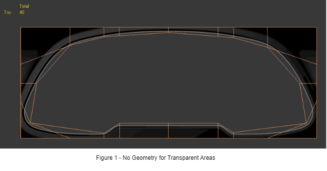
To avoid drawing fully transparent pixels, create special meshes that have no geometry where the texture would be transparent. These meshes don’t have to fit the texture exactly since they should only have very few polygons.
Refer to the following example: Instead of a single Billboard with 2 triangles this mesh uses 40, but also avoids a lot of transparent pixels in the center that otherwise would be drawn:
#### Optimize Number of Nodes
To reduce the number of draw calls object parts that share the same material and are not transparent can be combined into one single object.
#### Use Level of Detail (LoD)
For the best possible results, it’s also advised to create LoD-Meshes manually instead of using optimizer tools.
#### Lighting
Lighting is a costly operation so as few light sources as possible should be used. In terms of performance an ambient light is faster than a directional light which in turn is faster than a point light. The slowest light is a spotlight. In the Candera Graphics Engine, all light types can act as an implicit ambient light so in most cases there is no need to create an explicit one.
In any case, avoid scenes with partly covered lights (as might be done in real life). The same effect can usually be achieved with other but less costly techniques.
#### Textures
The general rule for textures is to make them as small as possible. Textures shouldn’t be bigger than the size they have when displayed on the target system. Though, depending on hardware limitations texture dimensions could be restricted to a power of 2.
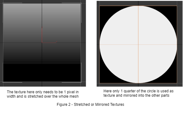
Textures can often be reduced further in size through clever usage of texture coordinates and stretching. If the texture is regular, it could be stretched or repeated or mirrored.
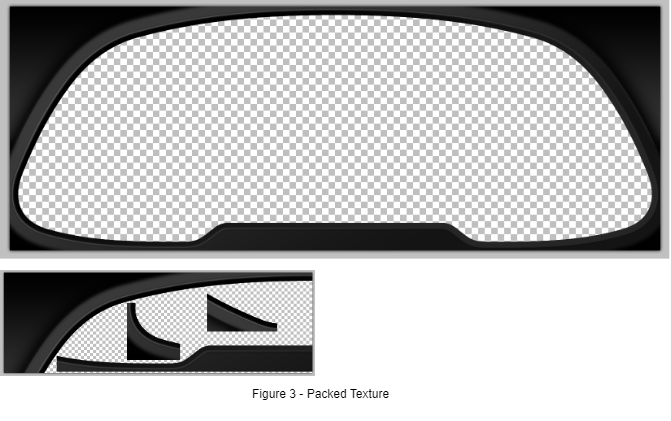
Also, large empty areas inside of textures should be avoided. This can be done by chopping up the texture and packing the filled parts as close as possible. Then adapt the mesh texture coordinates accordingly. A mesh with a few more polygons and a small texture is often faster than one with a big texture.
In above example, the texture is reduced to ¼ of the original size by cutting and packing parts closer together to avoid large empty areas. To display the object without errors again a special mesh needs to be created much like the one displayed in Figure 1.
Another possibility is to use 16-Bit Textures instead of 24/32-Bit to reduce the size of the content.
#### DCC Tool Specific Features and Capabilities
DCC Tool specific features and capabilities such as path extrusion, bone animations, shape morphing, particle effects, shadow casting, etc. are often either not transferable by simple export-import process or achieved in a different way on the target system. It is recommended to completely avoid these features or – if desired for early preview – not to rely on the availability of exactly these features on the target system. Nevertheless, most desired effects can be realized using specifically modeled objects and adding the regarding effect implementation with CGI Studio. How to implement a certain effect best needs to be clarified case by case with the Technical Artist implementing that effect for the target.
# Content Creation
### Formats supported by CGI Studio
#### 3D File Format: FBX
While import software (Autodesk FBX SDK) supports several file formats, due to limitations of different formats, Scene Composer supports FBX import only.
#### Supported 3D Content
- Mesh: Geometry as Array Buffer, indexed Array Buffer
- Nurb: converted to Mesh
- Patch: converted to Mesh
- Material: Ambient color, Diffuse, Emissive, Specular, Specular Power
- Light: Spot, Directional, Point
- Camera: field of View, near Plane, far Plane, aspect Ratio
- Animation: Translation, Rotation, Scaling, Visibility
- Scene Graph: Object position, deep Groups, flat Groups (i.e. linked objects)
- Skeleton: converted to Group
#### 2D Image and Texture Formats
A wide range of 2D content is supported for texture generation:
- Jpeg - .jpg, .jpe, .jpeg
- Portable Network Graphics - .png
- Graphics Interchange Format - .gif
- Truevision Targa - .tga
- Windows Bitmap - .bmp
- Tagged Image File Format - .tif
- Various others
During image export, **gamma correction must be disabled!**
####
### Content Creation Rules
#### Procedural Shaders
Procedural shaders and special hardware shaded materials are not supported by Candera and not exported by FBX plug-in. Use only textures and standard material properties like diffuse color, specular, emissive and ambient.
#### Procedural Meshes
Procedural generated meshes are not supported by Candera and not exported by FBX plug-in. Convert your procedural generated meshes to static meshes before exporting.
#### Reflective Materials
Reflective materials are ignored by Candera and not exported by FBX plug-in. Reflective effects have to be done by environment mapping in Candera.
#### Material Count
Only the first material of a mesh will be considered by Candera. All other materials are ignored.
#### Animations
A keyframe sequence cannot contain keyframes with different interpolation types. If a keyframe sequence has different interpolation types Candera takes only the interpolation type of the first keyframe into account. (linear, spline or step)
### Different Handling of 3D Coordinate Systems
Almost every 3D DCC tool uses an own interpretation of the 3D coordinate system. Due to this mix-up of coordinate systems, it is not always possible to mix the content of this DCC tools without any problems. Here some examples:
#### Autodesk 3ds Max
Autodesk 3ds Max uses +Z as up-vector and a right-handed coordinate system.
#### Autodesk Maya
Autodesk Maya uses +Y as up-vector and a right-handed coordinate system.
#### MAXON Cinema 4D
MAXON Cinema 4D uses +Y as up-vector and a left-handed coordinate system.
#### CGI Studio
The Scene Composer and the Candera rendering engine are using the default OpenGL coordinate system which is Y as up-vector and a right-handed coordinate system.
# Creating Content with various DCC Tools
As CGI-Studio is building on standard data formats like FBX, PNG, TIFF or TGA it is possible to use almost all modern digital content creation tools (DCC tools) to create 2D/3D content. Examples for 3D content tools are Autodesk 3DS Max, Autodesk Maya or MAXON Cinema 4D. Examples for 2D DCC Tools are Adobe Photoshop or Corel Draw. Usually, it is no problem to use many of them for one project but sometimes it can lead to problems because of the different creation methods these tools prefer. In this chapter we want to explain best practices in the CGI-Studio tool chain and how to overcome different obstacles you may face.
### General Recommendations
#### Use a single 3D DCC Tool
It is recommended to use only one 3D DCC tool for one project and not to mix content created from e.g. Cinema 4D and 3ds Max. This guarantees the best outcome without import problems. If there is a need to use more than one tool you have to be aware to fix import/export problems afterwards.
#### Mixing Content from 3ds Max and Cinema 4D
If you are forced to mix the content from 3ds Max and Cinema 4D you have to be aware that the handling of the coordinate systems is totally different. If you use an exported camera from Cinema 4D this camera usually has Y as up vector. So, if you load a 3D object from 3ds Max in the Scene Composer into a scene which was created by Cinema 4D you will see that your object is maybe rotated 90 degrees around the X axis. A simple fix is to rotate the object back -90 degrees around the X axis. However, by exporting the FBX file with option “Up Vector: Y” this can also be handled easy.
#### Use same FBX Plugin Version in whole Workflow
Using different FBX plugins within the workflow will may result in strange behavior and appearance of objects after importing them into CGI-Studio or when editing them in your 3D DCC tool after re-import with another plugin version.
The FBX versions are recommended as in the following table:
| **Scene Composer Version** | **FBX Version** |
| 3.3.0 | 7.4 or newer |
| 3.3.1 or newer | 7.4 or newer |
#### FBX Export Settings
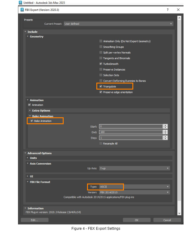
In general, we recommend starting with the default preset “Autodesk Media & Entertainment” and then manually setting the following options (Figure 4):
- Include -> Geometry -> Triangulate \[ON\]
(To ensure conversion of all polygons to triangles. Not available in some older FBX plugin versions.)
- Include -> Animation -> Bake Animation \[ON\]
(To preserve non-standard animations such as camera movement along a spline.)
- Advanced Options -> FBX File Format -> Type: ASCII
(Is human readable and easier to version in SCM tools.)
Only if you use a virtual Y-up axis” in 3ds Max (as shown in [Switching to a virtual Y-up Axis in 3ds Max](#bkmrk-switching-to-a-virtu)) then you should also set:
- Advanced Options -> Axis Conversion -> Up Axis: Z-up Tip: It’s advisable to save the modified export settings as new preset.
### Best Practice for 3ds Max
If you use 3ds Max alone for the whole project, then it is best to stay with its Z-up coordinate system. This means that you do not have to rotate every single object till it fits the OpenGL coordinate system used by CGI-Studio. The only thing you must consider when exporting a scene with the Autodesk 3ds Max FBX plug-in you have to choose Y as up vector to match the OpenGL coordinate system.
However, in some cases you may need to work with a Y-up coordinate system in 3ds Max. Examples are animations in 3ds Max which are to be combined with Cinema 4D content in Scene Composer. The following chapter shows how to setup a virtual Y-up axis.
#### Switching to a virtual Y-up Axis in 3ds Max
As 3ds Max uses “Z” as default up axis it is not possible with an in-built option to switch to another up axis. But with some tweaks you can change the up axis to “Y” and work within 3ds Max the same as you are working in a usual OpenGL coordinate system:
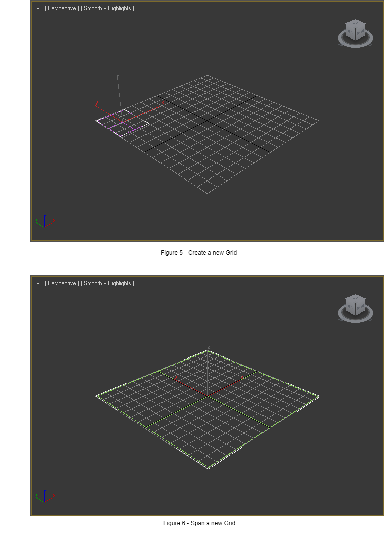
1\. Create a new Grid in the 3ds Max menu “Create” -> “Helpers” -> “Grid” and span the new Grid over the already existing one (refer to following two figures)
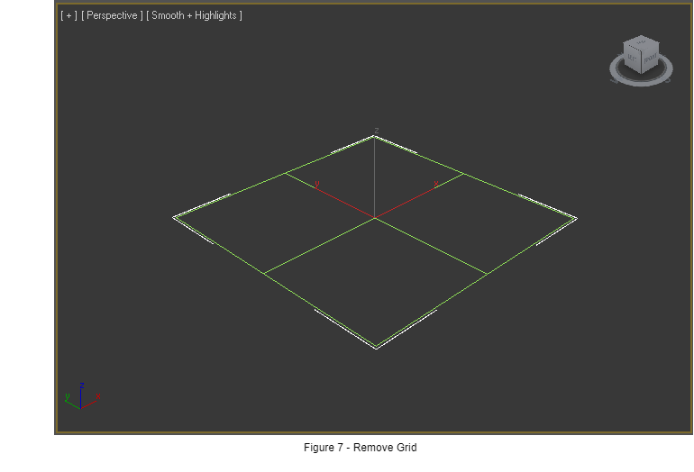
2\. Remove the existing Grid with the shortcut “G” in 3ds Max. (see the result in Figure 3)
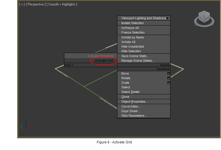
3\. Right click on the new grid an select “Activate Grid” from the context menu:
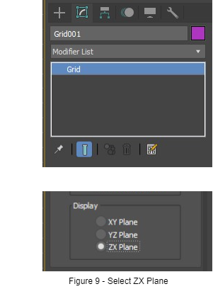
4\. Go to the “Modifier” Tab and change the Grid orientation to “ZX Plane”:
5\. Right click on the Grid, in the context menus select “Freeze Selection”.
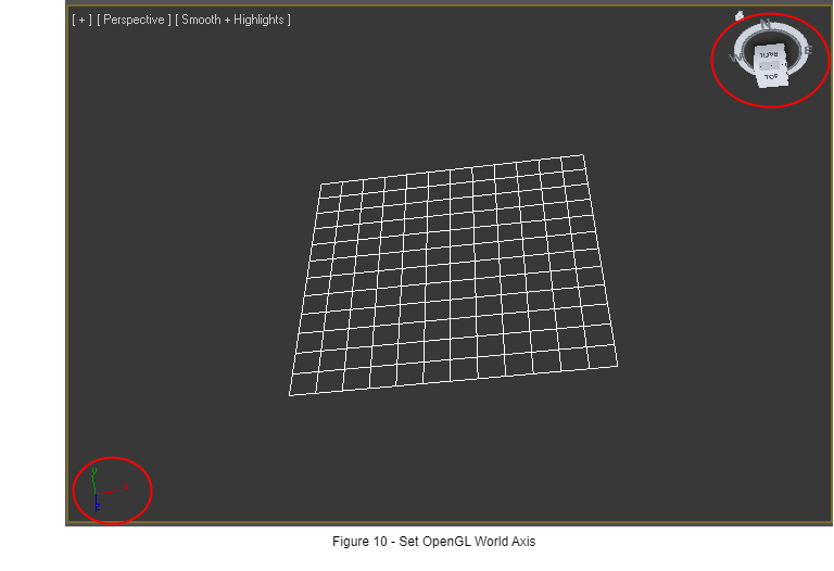
6\. Orbit the whole view to see the world axis like in OpenGL, which is Y-up, X-right, Z-front:
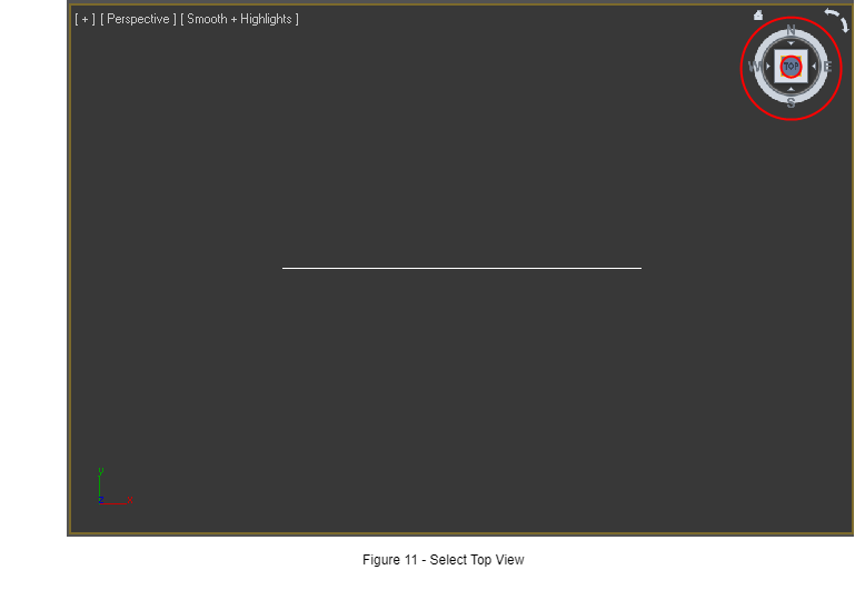
7\. Click “Top” on the View Cube to fix the view to a 100% “top view”. Please take care that the North-South-East-West is the same as in Figure 8.
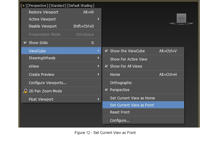
8\. As last step, click on the small plus (“+”) sign in the top left corner and select “View Cube” -> “Select current view as front”
You have created now a new “virtual” OpenGL view coordinate system and can work in 3ds Max with “Y” as up axis. (Hint: the easiest way to orbit around the scene is now with the help of the View Cube).
But please remember to export with the Option “Z” as up axis in the FBX Exporter when working in this way.
#### Render Settings Width and Height
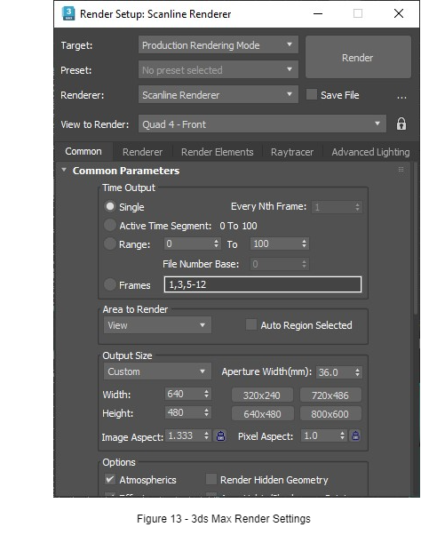
The 3ds Max FBX import plug in does not read out the film width and height stored in the FBX file. So, if you open a FBX file in 3ds Max and save it back again you have to take care to type in always the correct width and height of your project. Otherwise, the aspect ratio of the camera will not be calculated correctly, and you will have a distorted view in your project.
#### Camera “Near Range” and “Far Range”
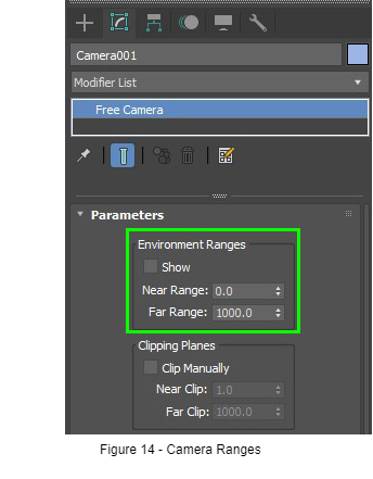
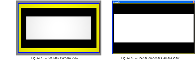
3ds Max has camera properties “Near Range” and “Far Range”. These values are imported correctly by CGI-Studio Scene Composer but 3ds Max does not take these values into account.
This means: If you create a camera in 3ds Max and look through the Camera on your scene then you can see always infinitely far into your scene. The Far Range has no limiting effect in 3ds Max. Please consider this when exporting the camera – it could be that you see your scene in 3ds Max but nothing in the Scene Composer because the Scene Composer (i.e., the Candera engine) always takes the near and far range into account.
####
Camera FOV
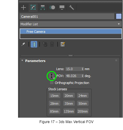
Sometimes, especially at wide angles, the camera field of view may appear different in SceneComposer from how it has been set up in 3ds Max:
That’s because in OpenGL the FOV angle is defined vertically while in 3ds Max the default is horizontal. Therefore, when working with CGI content always set the camera FOV to vertical within the 3ds Max camera parameters:
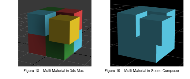
#### Multi/Sub-Object Materials
If multi materials have been assigned to (sub objects of) a mesh, only the first material is taken over into Scene Composer.
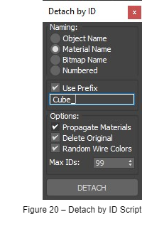
The easiest way to overcome this is to run the [Detach by Material ID](http://www.scriptspot.com/3ds-max/scripts/detach-by-material-id) script by Jefferson Lim. It splits the mesh into sub objects based on the different sub-object materials assigned to it.
#### Material Brightness Discrepancies
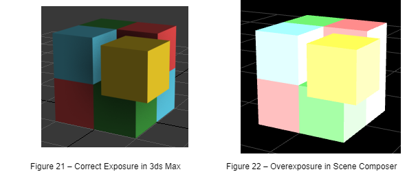
Often a scene which is lit just right in 3ds Max appears overexposed in Scene Composer:
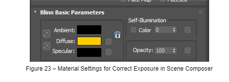
That’s due to differences how 3ds Max and Scene Composer handle Ambient and Specular material settings. To fix that kind of overexposure just make sure that Ambient and Specular are set to a dark color. Black might be a good start if no explicit highlights and ambient tones are used in the scene.
#### Affect Pivot only / Affect Object only / Affect Hierarchy only
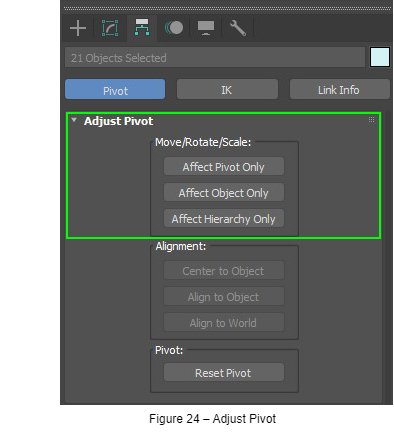
3ds Max has tools to move the pivot point of an object independent from the object itself. (Affect Pivot only / Affect Object only / Affect Hierarchy only) They are can be found in the Adjust Pivot section under the Hierarchy tab.
Our recommendation is to not use these tools but to create additional Groups in 3ds Max if Pivot functionality is needed. The reason for this is that 3D-Engines usually (like Candera) do not support independent Pivot Points from Objects. The recommended way to realize this feature is to generate empty Groups or Dummy Objects (“Null”-Nodes) and make the 3D object a child of the Group. After the 3D Object is a child of the (Pivot) Group or Dummy object the position of the Group serves as Pivot point for the object.
#### Fix 3ds Max files with translated Pivot Points
If you come across a 3ds Max or FBX file which already has translated (moved) Pivot Points, it can happen that this FBX file is not correctly imported by the Scene Composer. The experienced effect is seen as objects that are floating around in the scene at arbitrary positions. There are two ways to fix this:
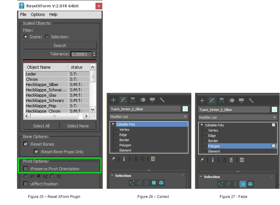
- Use the free [ResetXForm plugin](https://www.scriptspot.com/3ds-max/scripts/reset-xform) by PEN-Productions. For installation drag and drop the \*.mzp file into a Max viewport. Then go to “Customize – Customize User Interface… – Tab Toolbars – Category ‘PEN Tools’. Select ‘Reset XForm UI’ and drop it as new button on the Max toolbar. For correct script usage and configuration please see the following screenshots:
The most important option in the plug-in for fixing the wrong import of Pivot Points is the “Preserve Pivot Orientation” option in the ResetXForm plug-in (Figure 25). This option has to be **de-selected** to create a correct 3D Object for importing in the Scene Composer. (Tipp: You may permanently set the default state of this checkbox by changing the text entry “preserveOrientation=true” to “false” in the script file “PEN\_resetXformV2.ms”.)
Then you may select the objects you wish to reset – or just hit ‘Select All’ – and press ‘Reset X Form’.
You must ensure that none of the selected elements in the plugin’s object listing has an active sublevel selection (vertex, edge, border, polygon or element, as shown in Figure 26) otherwise single scene elements might be placed, scaled or rotated in an unwanted way.
- For scenes with flat object hierarchy, you may also use the ResetXForm functionality from 3ds Max (see 3ds Max documentation). Please keep in mind that objects in groups cannot be reset correctly by 3ds Max. You will have to move the object outside of any group to fix the Transform. You can move back the object into the group after the transform has been fixed.
#####
#### Animations are cut-off in Scene Composer
100 frames is the default animation length in 3ds Max. If you import an FBX file in 3ds Max which contains an animation with e.g. 200 frames, the animation will be cut off upon re-saving at frame #100 if you didn’t manually change the timeline length. (In fact the keys after #100 are not deleted but still remain in the FBX. They are just ‘hidden’ by a lower “TimeLineStopTime” value.)
**Solution:**
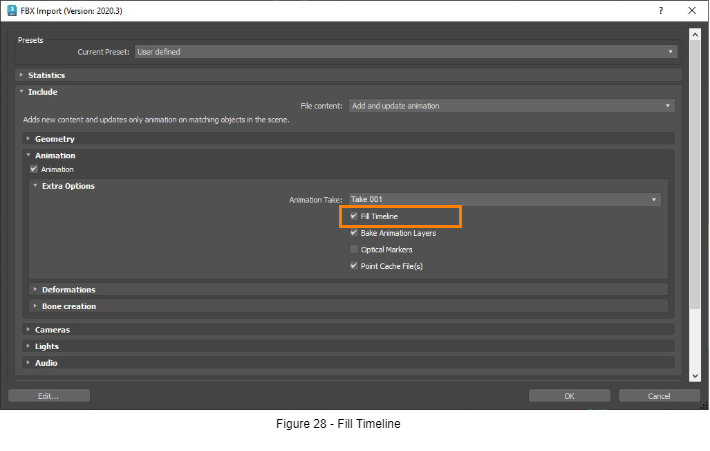
- Activate „Fill Timeline” (Figure 28) when importing an FBX into 3ds Max. Then the animation timeline is automatically updated in 3ds Max to the correct length.
- Unfortunately this is not the default setting within the importer but remembered if changed once.
##### Animations along a Path don’t work after FBX Export
In 3ds Max you can animate objects along a path or spline. After FBX export this kind of animation may not work anymore.
**Solution:** Activate “Bake Animation” as described in [FBX Export Settings](#bkmrk-fbx-export-settings).
#### Best Practice for Cinema 4D
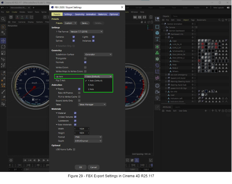
Cinema 4D uses Y-Axis by default as an up-vector and it can be changed to X-Axis or Z-Axis when exporting to FBX in the Geometry section as demonstrated in Figure 29.
#### Best Practice for Maya
##### Pivot Point
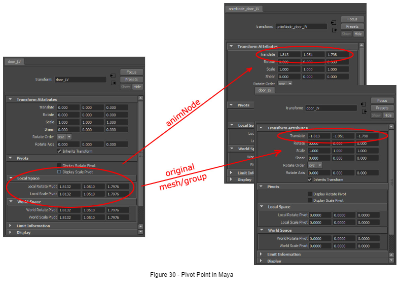
The Local Rotate Pivot and Local Scale Pivot of an object can’t be exported to CGI Studio; all transformations need to be done in the world coordinate system. To simulate a local rotate or scale point, the object can be put under an additional group which translates the objects to the desired position of the local pivot, while the translation of the object itself reverses this translation. See the screenshot for an example. Animating the group will then have the same effect as using a local pivot point.
### General Pitfalls
#### Empty FBX Import in Scene Composer
Sometimes instead of showing the new content the Scene Composer import dialogue stays empty after importing an FBX file. This happens mainly on Windows XP systems and seems to be a problem with external system components which may be resolved by future updates. Until then following workarounds may help:
1. Close the import dialogue and retry a few times to import the FBX. Sometimes each 2nd to 5th try may work.
2. If your scene contains special geometry like NURBS convert it all to meshes before exporting to FBX.
3. Only export part of the scene and try to import into Scene Composer part by part.
# Creating a 3D Font for CGI Studio
The scope of this section is providing step-by-step instructions for creating a 3D font which can be used within the CGI Studio tool chain.
### Overview
Any TrueType font can easily be adapted for use within the CGI tool chain. All needed is an FBX file containing a set of meshes which represent the 3D letters of the font. The name of each character mesh within the set must end with a four-digit code, the so called “code point”, which identifies a character in Unicode space.
All character meshes within the set must be aligned at the same baseline and at their left ends, resulting in a 3D scene with all character meshes being stacked on top of each other.
A single helper object, a “dummy” in 3ds max, is placed at the left end and baseline of the meshes. It not only serves as the root object within the scene hierarchy but will also become the anchor point, a kind of “physical” pivot, for character manipulation (moving, rotating, resizing) within CGI font widgets at a later step.
### Creating a 3D Font in 3ds Max 2023
#### Get Name Suffix for the Character Mesh
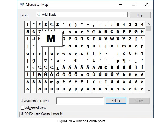
For being automatically identified within CGI Studio the name of each character’s mesh must end with the four digits Unicode code point. If working in Windows, you can find this hex value using the Charmap (Windows -> Start -> Run… “Charmap”). Just select a letter and look up its four-digit code point in the bottom left corner.
In Figure 29, the value of the selected letter “M” is “004D”.
The code points may also be found on the Internet (e.g.: [http://www.utf8-chartable.de/](http://www.utf8-chartable.de/)).
#### Create First Character
1. Start 3ds Max.
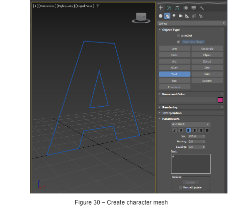
2. Create -> Shapes -> Text
Choose desired font (in our example “Arial Black”), set Size to e.g., 100, type a character into the text field (e.g. “A”) and then, preferably in the “Front” viewport, place the character on the grid.
3. Give the mesh a meaningful name (without using special characters or spaces) and as suffix add the Unicode code point explained in chapter [Get Name Suffix for the Character Mesh](#bkmrk-get-name-suffix-for-). Valid names would be “Letter\_A\_0041”, “PlusSign002B” or just “007A”.
4. Finally set the mesh position to 0,0,0.
#### Extrude Character
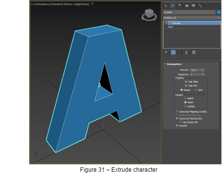
Modifiers -> Mesh Editing -> Extrude -> Set “Amount” to e.g., “-10”.
#### Clone and Create Remaining Characters
1. Select the character mesh -> Edit -> Clone
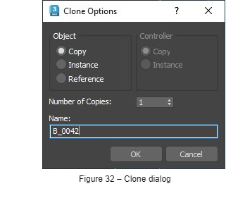
2. Set “Object” to “Copy” and enter a name for the new character.
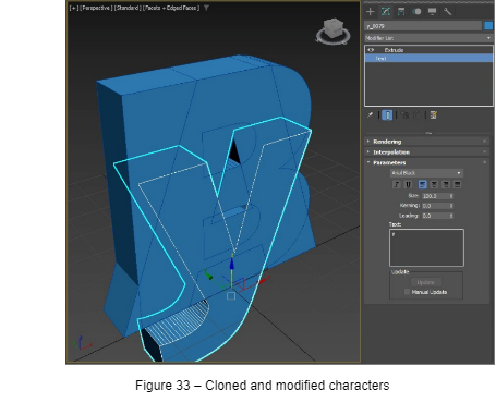
3. Go to the Modify panel -> select the “Text” object -> replace the character in the text field with new one. You should now see two overlapping character meshes in your viewport.
4. Repeat until all needed characters are created.
#### Anchor Object
Currently the pivot point of each mesh is set to 0,0,0 – therefore positioned at each character’s Z-baseline Y-front and X-center (given that Z is the up axis in the scene).
However, for usage within CGI Studio we need an anchor at the left side of the characters and at the center of their Y (depth) dimension. Moving the pivot point won’t serve that purpose because pivot settings will be ignored later in the tool chain. So, we have to introduce a dummy which will become the root object of all character meshes and will serve as pivot or anchor point for object manipulation within CGI Studio.
##### Align the Character Meshes
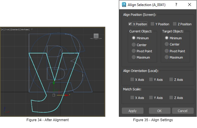
To ease the process, we first align all character meshes along their left minimum:
1. 1. Select all character meshes -> Tools -> Align -> Align… -> Edit -> Select by -> Name
2. While the align cursor still is visible select any character mesh in the “Pick Object” dialog and press “Pick”.
3. In the “Align Selection” dialog remove all checkmarks except for “X Position”. Set “Current Object” and “Target Object” to “Minimum” and press “Apply”.
##### Anchor Creation and Positioning
1. 1. Create -> Helpers -> Dummy
Drag the mouse inside the viewport until a rectangle – or in perspective view a cube – becomes visible. Tipp: Always keep dummies very small in relation to the meshes to prevent their bounding boxes from cluttering the viewport later on.
2. Assign some meaningful name to the dummy, e.g., in our case the font name: “Arial\_Black”.
3. Set the dummy’s Z position to “0”, so its pivot is aligned with the character baseline.
4. For aligning X and Y we again need the align tool. Select the dummy and as learned in 5.2.5.1, pick any character mesh as target object.
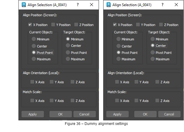
2. 1. In the “Align Selection” dialog again remove all checkmarks except “X Position” but this time as “Current Object” set “Pivot Point”, as shown in Figure 36. “Target Object” again is “Minimum”. Click “Apply” to leave the dialog open after X alignment.
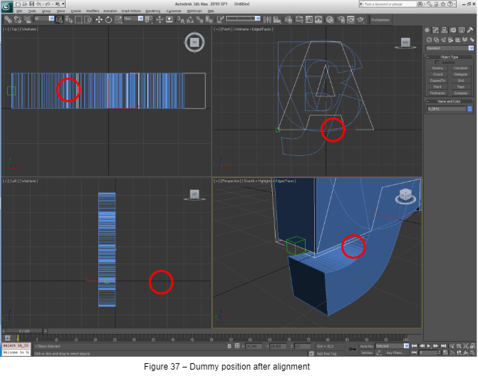
2. Now remove the “X Position” checkmark and check “Y Position”. Change “Target Object” to “Center” and click “OK”. (Note: If Y is your up axis you might have to align along Z instead of Y.)
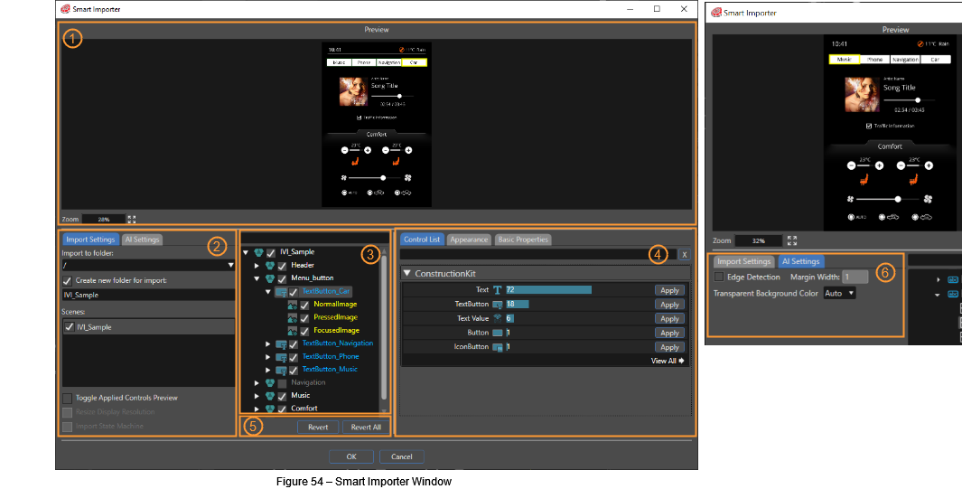
| (1) | Preview | The preview panel displays a preview of the graphics file o be imported. You can use the mouse wheel to zoom in and out, with the zoom percentage displayed in the lower left corner of the preview panel. By pressing the button displaying four arrows, you can modify the preview image’s size within the panel’s maximum available space.
By clicking within the preview panel, you can select design elements from the displayed image. The AI will then attempt to detect and define a suitable control for the selected element.
|
| (2) | Import Settings | The import settings panel will allow you to select a destination folder to import template solutions. You can choose to create a custom imports folder, which will be created inside the destination folder.
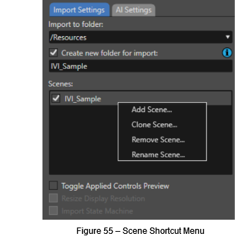
In the Scenes section below, you can edit template scenes you are configuring with the Smart Importer. Use the shortcut menu to add, clone, remove, or rename scenes. To make modifications to the content from a particular scene, select the scene in the import settings panel (2), then check or uncheck the checkboxes next to the desired layers and controls in the layer tree (3).
With the “Toggle Applied Controls Preview” checkbox enabled, you can verify which portions of the displayed graphic already have a control applied to them. Portions which already have a control applied will be marked with a green outline in the preview panel (1).
By checking the “Resize Display Resolution” checkbox, the imported design will automatically resize itself to fit within the display resolution configured for your solution.
The “Import State Machine” option allows you to import state machines from your design file directly to your CGI Studio solution. If a global state machine already exists within your solution, a prompt will be displayed in which you can choose whether or not to import the new state machines with the **IsGlobal** property enabled.
|
| (3) | Layer Tree | The layer tree panel will display the elements imported from your graphic file as a branching list. The list displayed within this panel is equivalent to the template scene’s Scene Tree within Scene Composer. You can select one or multiple items within this list to begin the AI detection process. The filter bar located on top of the layer tree will allow you to more easily identify a specific layer when dealing with multiple layers.
Using the checkboxes, you can decide if a layer is part of the scene that is currently selected in the import settings panel (2). If you uncheck a layer’s checkbox for all scenes, the layer will not be imported.
|
| (4) | Control List, Appearance and Basic Properties | By selecting a layer, the AI will attempt to detect which controls are suitable for the selected elements. The result of this analysis will be displayed in the **ControlList** panel, listing the candidate control from greatest to least probability. The list of controls can also be filtered using the input field on the top. Use the “Apply” button in the control list to apply a control to the selected element. If the AI has detected only a weak probability for your selected control, you will be prompted to confirm your choice.
After applying a control to a design element, you can then configure the control’s properties using the **Appearance Tab**. For example, you could select two images to represent both TellTale states, or modify the position of the pivot point for the gauge’s needle image. You can modify additional properties in the **Basic Properties** tab.
|
| (5) | Revert & Revert All | You can select an item in the layer tree panel (3) and revert the already applied control using the “Revert” button. You can choose to revert all applied controls in the “Layer Tree” by pressing the **Revert All** button. You will be prompted to confirm this action in order to keep you safe.
|
| (6) | AI Settings | In the AI Settings you can change the Transparent Background Color for AI detection. The selected color is used by the AI to analyze the graphics to be improved. It pretty much depends on the content of the image, which transparent background color works best for detecting controls. IN case the AI is having problems in detection controls, you can try to change this setting.
|
#### Configure Scenes
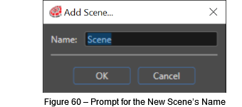
In the Import Settings Panel you can manage the scenes you want to import into Scene Composer. Opening the shortcut menu, you will see the available options: Add Scene, Close Scene, Remove Scene, and Rename Scene. Double-clicking on the scene’s name allows you to rename an existing scene.
The AddScene and Remove Scene options will be disabled when multiple scenes are included within the imported Intermediate Language file.
##### Configure the Scene’s Content
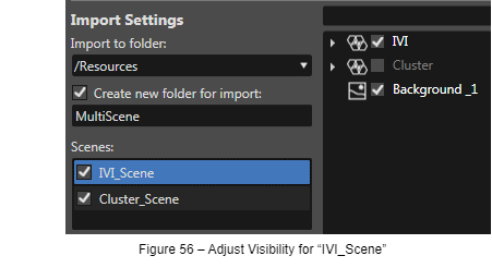
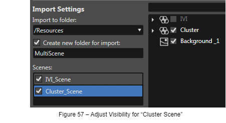
Let’s assume you got a graphic file from your designer with 2 scenes, an **IVI scene** (e.g. with a music player and climate control) and a **Cluster scene**. You will create two scenes in the **Import Settings** panel: an “IVI\_Scene” and a “Cluster\_Scene”. Select the “IVI\_Scene” and adjust the visibility of the layers in the **Layer Tree** panel – only “IVI” and “Background\_1” will be checked. Handle the “Cluster Scene” similarly – only “Cluster” and “Background\_1” will be checked.
Clus
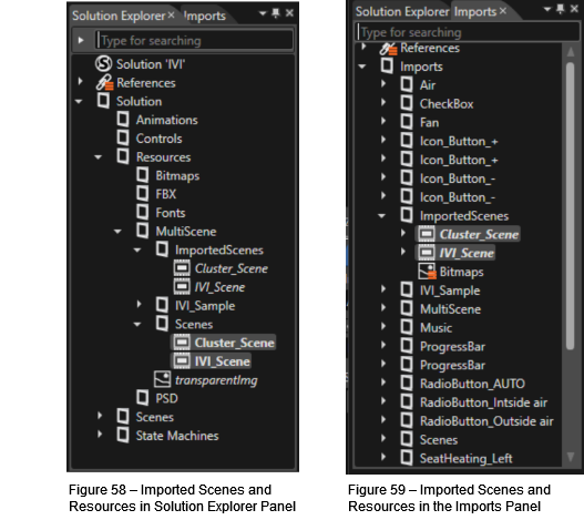
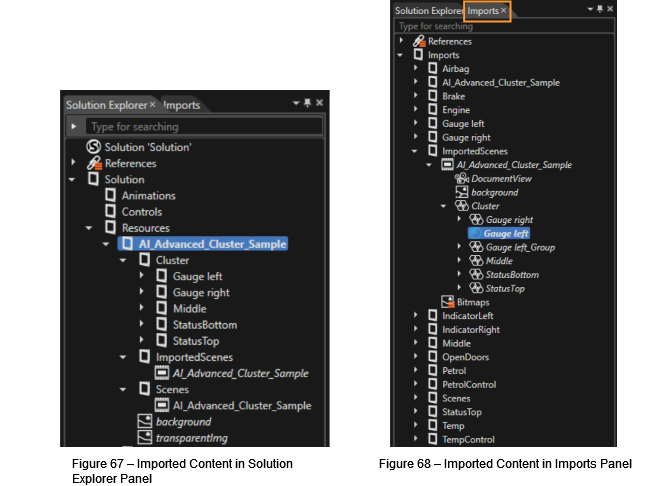
When clicking the **OK** button, the import is started. You can then see the imported scenes and resources in the Solution Explorer panel and in the Imports panel of Scene Composer.
#### Detection, Configuration and Import of a GaugeControl
When you import a graphics file that includes a gauge using the Smart Importer the AI will detect this control and import the template scene including the correctly identified gauge control-
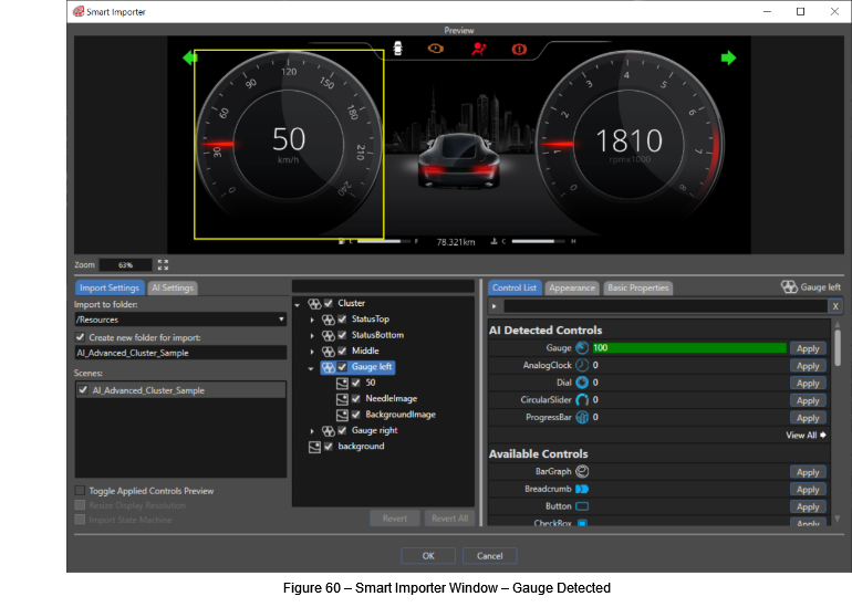
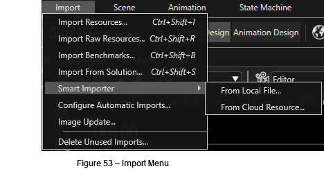
To make the AI detect the gauge in your graphics file, open the graphics file with the Smart Importer (via the Menu: Import – Smart Importer and choose your graphics file). Your graphics file will be displayed in the “Preview” panel.
Now you can select your gauge by clicking on the corresponding graphics in the “Preview” panel. The Layer Tree panel will expand the layers and mark the layer you selected.
As an alternative, you can browse to the desired layer in the “Layer Tree” panel. If you know at least part the layer’s name, you may use the filter field in the top of the Layer Tree panel to find the correct layer more easily. The content you select in the “Layer Tree” panel will be highlighted with a yellow frame in the “Preview” panel.
Whenever you select any content – no matter if selecting single layers or multiple layers – the AI tries to detect known controls. You can see the list of detected controls in the “Control List” panel on the bottom right.
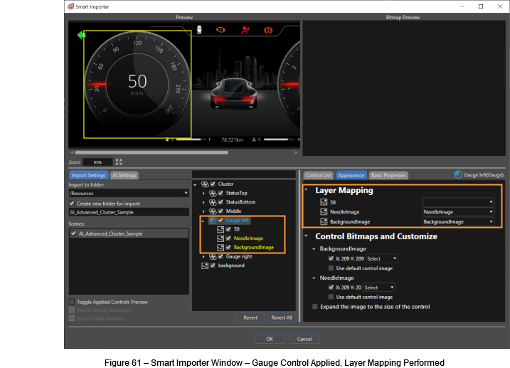
In our example the AI correctly detected a Gauge Control, so you will press the “Apply” button on the right. The Appearance Tab is put to the foreground, offering you the possibility to configure the GaugeControl’s NeedleImage and BackgroundImage. After performing this Layer Mapping, you will see the GaugeControl Layer in the “Layer Tree” panel and its content will be colored, indicating a successful application of the GaugeControl (blue font) and a successful mapping of the image (yellow font).
##### Configure the Pivot Point
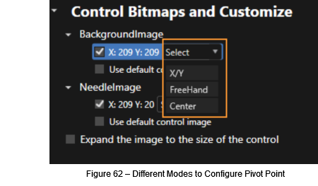
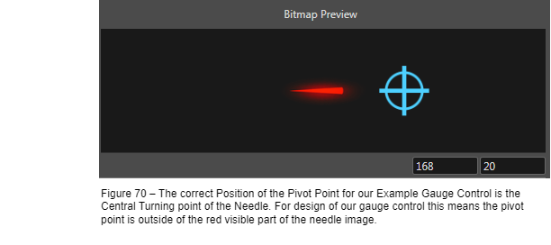
For all images configured in the Layer Mapping, you can configure the pivot point in the Appearance Tab on the bottom right. In our example for the GaugeControl it is important that the pivot point of the needle image is set correctly in order to guarantee the correct movement of the needle in Scene Composer.
There are 3 ways to configure the pivot point:
- Enter digits for the **X/Y** coordinate.
- **Freehand** position a crosshair cursor using the mouse.
- Configure the pivot point to be in the center of the image.
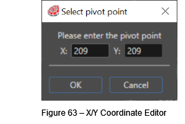
- **X/Y:** You can choose this option to enter the X/Y coordinates for the pivot point in the following editor.
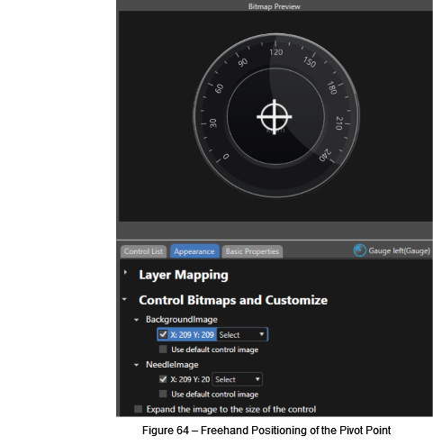
- **Freehand:** If you choose this option, you can move the crosshair cursor to the desired pivot point in the “Bitmap Preview” panel.
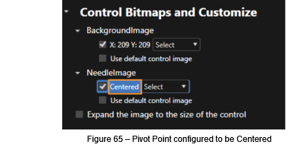
- **Center:** With this option, the pivot point will be configured to the center of the image. A center configuration of the pivot point will be indicated by the text “centered” in the Appearance tab.
##### Configure Basic Properties
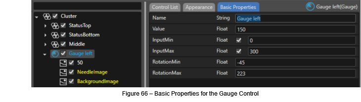
The controls have been detected by the AI and you have applied them to your layers. In the appearance tab you have mapped your layers to images that are part of the controls (i.e. the gauge’s needle image and the background image). You can also define values for basic properties of the applied control.
The following basic properties are available for the gauge control. To easily find our gauge control instance in Scene Composer after the import, you may also change its name to e.g. “Gauge\_for\_speed”.
Individual properties from your design will be automatically mapped if the property’s name is the same as the control’s property name.
##### Import to Scene Composer
Once you are finished applying the detected controls and configuring images, pivot points and other properties, click the OK button to import your configured file.
You can now see that the folder “AI\_Advanced\_Cluster\_Sample§ has been created and the content of your psd file has been imported. The gauge control instance “Gauge\_for\_speed” you configured using the Smart Importer can be found in the “Imports” panel.
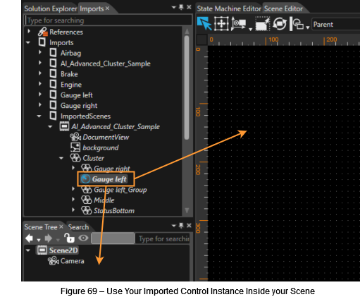
You may create an instance of your “Gauge\_for\_speed” by dragging it into your scene – either into the Scene Editor panel or into the Scene Tree panel.
#### 7.3.5. Layer Merging
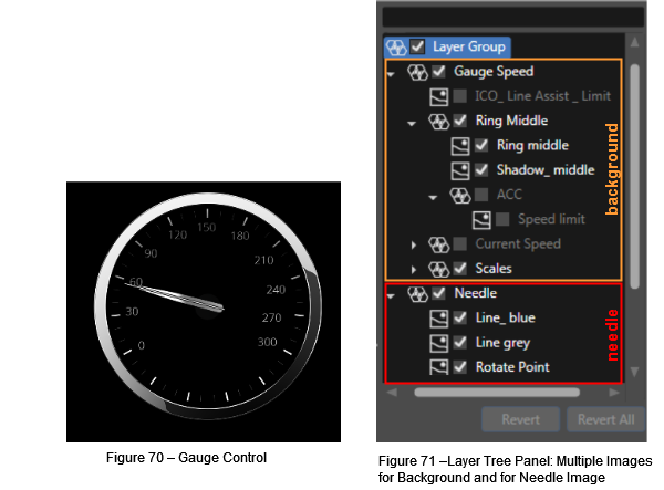
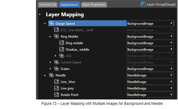
Sometimes the graphics file to import will be quite complex, having several images for a gauge’s background and a few images for a gauge’s needle to achieve a brilliant HMI. The built in GaugeControl of Scene Composer however requires only one image for the background and one image for the needle. To meet the needs of both, complex graphics files and a clear implementation and configuration of the control, the Smart Importer is able to configure several layers for a single image of the control.
In the following example the layers for the gauge’s background are marked in orange and the layers for the needle are marked in red.
Select the root of the gauge in the “Layer Tree” panel that includes both the background images and the needle images. In our example this layer is called “LayerGroup”. In the “Control List” panel you will see that the AI has detected the GaugeControl. After pressing the “Apply” button next to the GaugeControl you can map the layers to the GaugeControl’s background and needle image.
**Useful Hints:**
- You can configure a complex layer group by selecting and configuring only the root. All its children will be configured similarly.
- You can select multiple layers and configure them all at once. For multi selection you can keep the <ctrl> or <shift> key pressed while selecting the layers with a mouse click or you can click-and-drag a box around the layers you want to select.
Finalize the configuzration of your GaugeControl by setting the NeedleImage’s pivot point to exactly that point where the needle should rotate around as described in [Configure the Pivot Point](#bkmrk-configure-the-pivot-).
After the configuration is complete you can press the “OK” Button of the Smart Importer to import your graphics file and the configured GaugeControl Instance into SceneComposer.
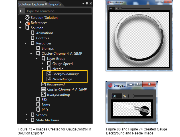
Smart Importer has created a single image for the needle and a single image for the background as you can see in the Solution Explorer.
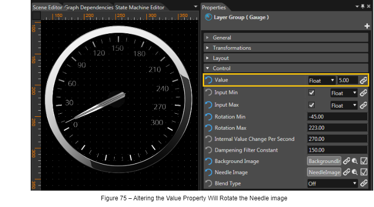
To test the functionality of the GaugeControl, drag and drop the configured GaugeControl instance to the scene (as described in [Import to Scene Composer](#bkmrk-import-to-scene-comp)). When altering the GaugeControl’s value in the Properties panel, the needle of the GaugeControl in the Scene Editor panel will rotate in front of the background according to the alteration of the Control’s value.
#### Re-Importing of Graphics Content
When importing the same content to the same location once again, the resources and scenes in Scene Composer are overwritten. This allows you to replace outdated graphics of your scene with newly updated graphics from your designer while maintaining the mapping between layers and controls.
##### Reload Configuration for New Graphics File
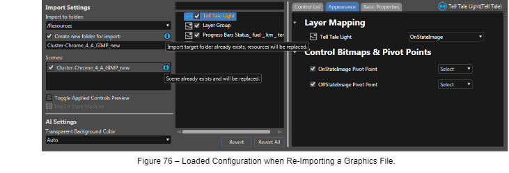
If you use the Smart Importer to open the same graphics file (same path, same filename) again, which you have already made configurations to, you will see your configurations are available again (marked with orange font in the layer tree panel). The applied controls as well as the Layer Mapping have been loaded.
You will be notified by blue information icons that the import target folder or the scene already exist (A tooltip gives you the necessary information once you hover those icons). Starting the import as currently configured will overwrite already imported resources and scenes and therefore update the graphics of your Scene Composer solution to the newest graphics version, while keeping the information of mapped layers and applied controls.
If you want to import graphics content to your Scene Composer solution for a second time, maintaining the resources and scenes from both imports, you can choose a different import location or a different scene name.
##### Re-Import of a Graphics File with Different Layers
When importing a graphics file with the same path and filename but partially different layers, you will see the configuration of the layers that are still available has been loaded.
- The orange font indicates that a bitmap from the node assigned to the control is currently in use within another control.
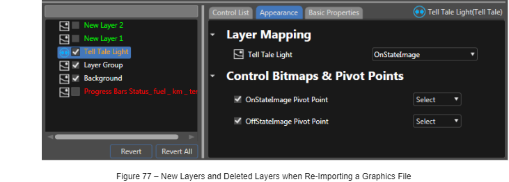
- Layers that had not been part of the graphics file before will be displayed in green font. They are not visible in the preview panel since they are disabled by the layer tree panel’s checkbox.
- Layers that are missing in the currently loaded file are displayed in red font in the layer tree panel. The content of layers that are not available in the currently loaded graphics file cannot be displayed since the image data is simply missing. Checking the checkbox in the layer tree panel won’t make any change in the preview panel.
##### Restore a Configuration
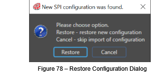
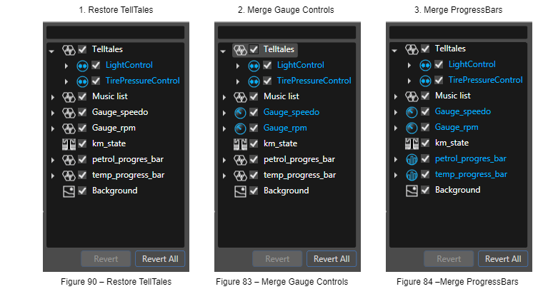
If you have already imported a graphics file into a certain folder and you are attempting to import the same graphics file to the same folder again, the Smart Importer will load the configuration you applied last time. If you are reverting your configuration using the Revert All button, the loaded configuration is gone. However, the configuration of the last successful import is still saved with the lastly imported scene. So, changing the import location and changing it back to the original import location, where the configuration is saved, makes a dialog pop up asking you whether you want to restore the saved configuration.
Choose Restore to restore the configuration from your last import or Cancel to start configuring all over again.
##### Merge Configurations
A configuration that has been imported to Scene Composer is saved to the imported scene. You can use one graphics file, import various configurations to Scene Composer and merge them together into one final configuration.
**I. Create Configurations**
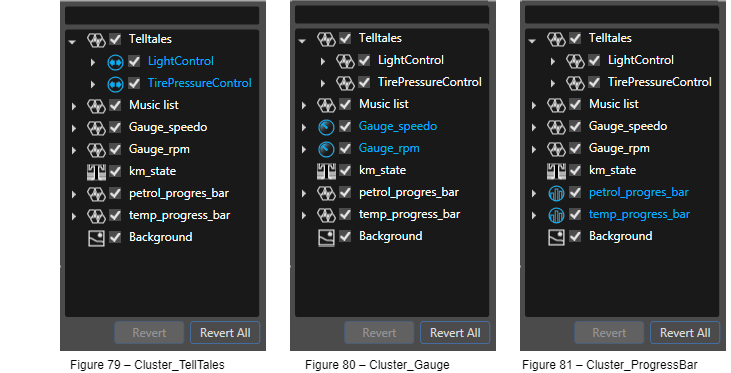
1. Open your Cluster graphics file using the Smart Importer, configure the Telltale controls and import them to folder Cluster\_Telltales for example.
2. Open the graphics file again and configure the Gauge Controls; import them to folder Cluster\_Gauge.
3. Once again open the graphics file and configure the ProgressBar Controls; import them to folder Cluster\_ProgressBar.
**II. Merge Configurations**
1. If you now open the Cluster graphics file again and set the import folder to Cluster\_Telltale you can restore the configuration for your Telltale controls by clicking Restore in the [Restore a Configuration](#bkmrk-7.3.6.3.-restore-a-c) dialog.
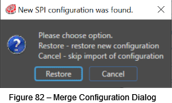
2. Now, change the import folder to Cluster\_Gauge, which triggers the following dialog, where you choose Merge to add the Gauge configuration to the currently loaded Telltale configuration.
3. Change the import folder to Cluster\_Progressbar and merge the configuration of the progressbars to your currently loaded and merged configurations.
And finally, you’ll end up with a configuration having applied TellTale Controls, Gauge Controls and ProgressBar Controls.
#### Advanced Configuration of PSD Content for Import to Scene Composer
##### Import Bitmap Resources
Images of Image Layers in psd data are imported as Bitmap Resources. By default, the value of the Pivot Hint of imported Bitmap Resources is calculated to be in the center as follows:
Pivot Hint X = Image Layer width /2
Pivot Hint Y = Image Layer height /2
You can set the Pivot Hint in Photoshop by embedding the token into the layer’s name. The Pivot Hint tokens are removed from the Bitmap Resource name upon import.
**E.g. 1:** If the layer’s name in the photoshop file is "Image@X30.5@Y40"
the Bitmap resource name will be “Image”,
Pivot Hint X = 30.50
Pivot Hint Y = 40.00
**E.g. 2:** If the layer’s name in the photoshop file is "ImageData@Y40.55"
the Bitmap resource name will be “ImageData”,
Pivot Hint X = "ImageData@Y40.5" layer width / 2
Pivot Hint Y = 40.55
##### TextStyle
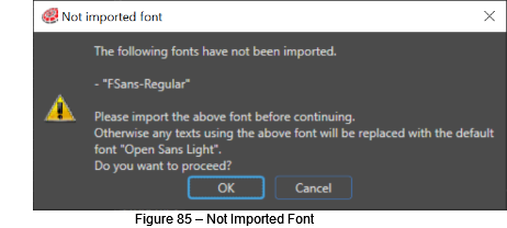
When importing a Text Layer into Scene Composer, a new TextStyle is created. Its name will be a combination of the font name and the font size used in the Text Layer of the PSD file. Upon creation of a new TextStyle Scene Composer checks if a font resource with the corresponding name is registered in the Scene Composer solution. In case no suitable font resource has been found in the solution, a new TextStyle will be created using the font resources displayed in the “Not imported font” dialog.
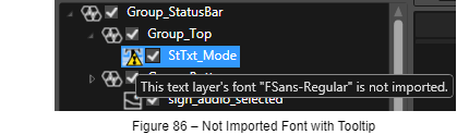
Fonts that are not imported are also marked with a warning sign in the “Layer Tree” panel. A tooltip offers additional information:
### Technical Details
#### Collaboration of Scene Composer, ControlsAIService and ControlsAIApp
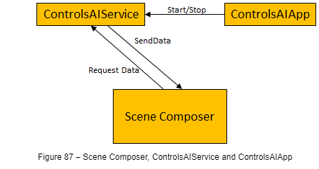
Scene Composer comes with two additional applications that are needed to make the AI detection work:
- **ControlsAIService:** A windows service application that provides the AI data for Scene Composer.
- **ControlsAIApp:** A tray icon application that controls the service.
The following diagram explains the collaboration of the Scene Composer, the ControlsAIService and the ControlsAIApp:
#### XML Scene Composer Intermediate Format – XSCIL
XML Scene Composer Intermediate Format (XSCIL) is an open and well-defined format which has been invented to export graphics data from various user experience design tools (Axure RP, Adobe XY, Sketch etc.) and import them into Scene Composer via the Smart Importer. An API is available which you can use to implement an exporter for your favorite graphics editor, if it isn’t already available.
#### Recommended Photoshop (.PSD) Layer Structure for Smart Importer
These are the recommended steps for Photoshop layers’ naming and structure of a Control when creating a PSD file with Adobe Photoshop. Tis procedure makes it easier to apply properties to a Control via the Smart Importer.
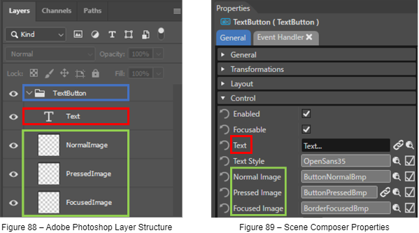
1. Create a group for the target Control – in this case, a TextButton (blue highlight in Figure below)
2. Create layers for the properties of the Control under the group created in step 1. (red and green highlight in Figure 88 below)
3. Set the names of the layers to be the same as the property names of the target Control. (layers names in Figure 88 below correspond to property names in Figure 89)
How to set appropriate group and layer names:
- The group name is arbitrary.
- For the layer name, use the property name but remove the spaces. For example, “Normal Image” becomes “NormalImage”.
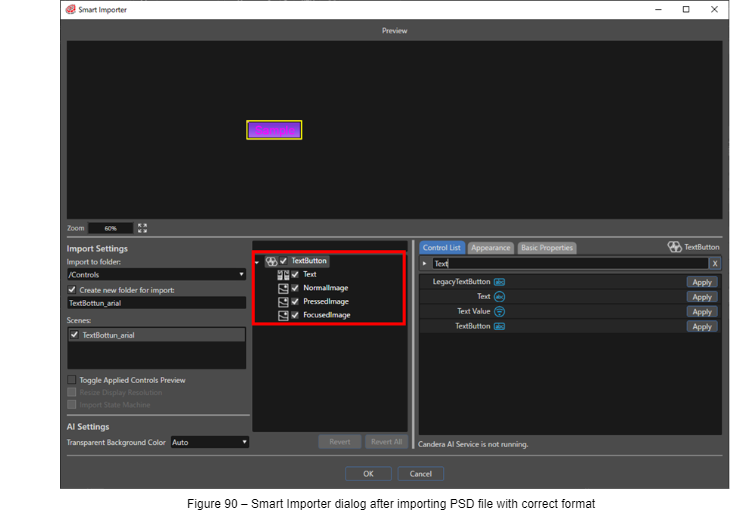
Figure 90 shows the Smart Importer dialog when a PSD file following the correct format is opened.
It is imported according to the layer structure of the PSD file.
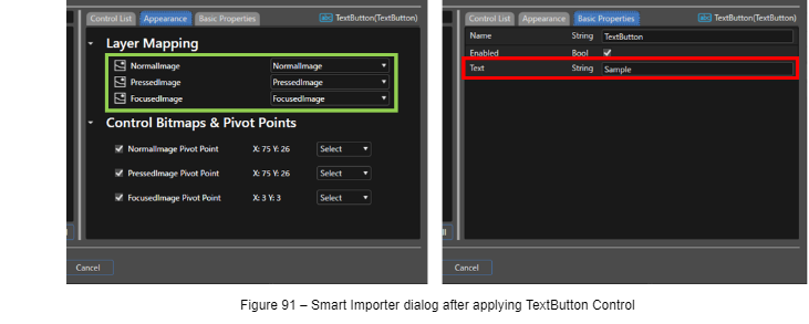
In the Smart Importer dialog, if you apply the TextButton control to the TextButton node, the layers of the PSD file will be reflected in each property as shown in Figure 91.
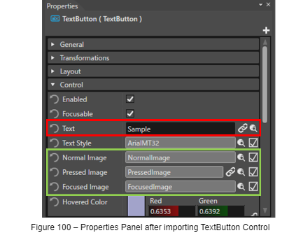
Figure shows the Properties panel after import settings shown in Figure 91. The contents/layers of the PSD file are reflexted in the Properties panel.
The size of the imported Control will be adjusted to the Width and Height of the largest image layer applied to a property.
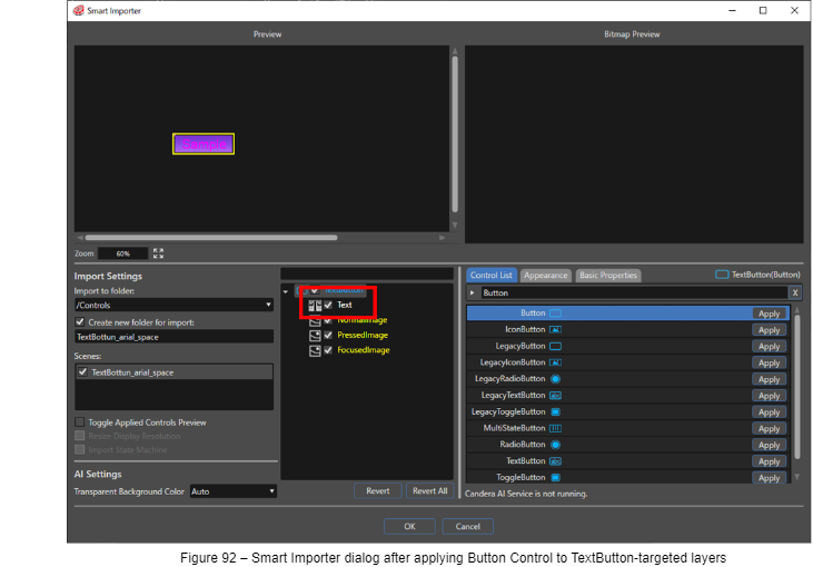
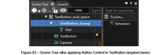
In Figure 92, when Button is applied instead of TextButton, Text property is not applied correctly since a Button control does not have this property.
| **AnalogClock** | **Breadcrumb** | **CheckBox** |
| - SecondsNeedleImage
- MinutesNeedleImage
- HoursNeedleImage
- FaceImage
| - Name
- EllipsisText
- Button
- NormalImage
- PressedImage
- FocusImage
| - NormalImage
- PressedImage
- SelectedImage
- SelectedPressedImage
- FocusedImage
|
| **CircularSlider** | **Gauge** | **GroupBox** |
| - BackgroundImage
- ActiveImage
- ThumbImage
- ThumbImagePressed
- FocusImage
| - NeedleImage
- BackgroundImage
| - BackgroundImage
|
| IconButton | InputField | Menu Icon |
| - NormalImage
- PressedImage
- FocusedImage
- IconNormalImage
- IconPressedImage
- IconFocusedImage
| - CaretImage
- BackgroundImage
- FocusedImage
| - Image
- BackgroundImage
|
| **Menu Item** | **Menu Screen** | **Mesh2D** |
| - FocusImageOnSelection
- FocusImageOnDragging
- DeleteButtonNormalImage
- DeleteButtonPressedImage
- Image
| - BackgroundImage
- FocusBorderImage
| - Image
|
| **MultiStateButton** | **PageIndicator** | **RadioButton** |
| - ButtonState1Bmp
- ButtonState2Bmp
- ButtonState3Bmp
- ButtonState4Bmp
- FocusedImage
| - PressedImage
- SelectedPressedImage
- SelectedIndicatorImage
- IndicatorImage
- SelectedIndicatorPressedImage
- IndicatorPressedImage
| - NormalImage
- PressedImage
- SelectedImage
- SelectedPressedImage
- FocusedImage
|
| ** Roll** | **SpinBox** | ** TextButton** |
| - DecorationImage
- TextEditBackground
| - BackgroundImage
- ArrowUpNormalImage
- ArrowUpPressedImage
- ArrowDownNormalImage
- ArrowDownPressedImage
| - Text
- NormalImage
- PressedImage
- FocusedImage
|
| **ToggleButton** | **TouchIndication** |
|
| - FirstImage
- FirstPressedImage
- SecondImage
- SecondPressedImage
- FocusedImage
| - Image
|
|